


Patents Completed.
Page 20
If you've noticed an error in this article please click here to report it so we can fix it.
Radiator without Sweated Joints. Combined Clutch and Gearbox.
W. S. TYLER, NO. 29,777, dated 27th December, 1912.— The accompanying illustration shows a construction of radiator in which soldered joints are entirely dispensed with. The headers are spud apart by means of side plates bolted on, and their adjacent faces are drilled with a number of holes
to form the tube plates. These holes are fitted with indiarubber ferrules which have a central groove to fit the tube plate.
The, tubes are easily sprung into position through these ferrules, which form a water-tight joint. Radiating fins, if provided, are not cast right up to the edges of the tubes.
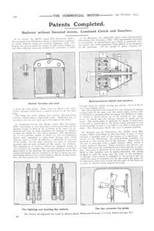
G. CONSTANTINESCUE, No. 26,161, dated 14th November, 1912.—According to this invention a small proportion of the gaseous charge in each of the cylinders of an engine is abstracted and may be used separately for heating or lighting or may be stored for any other purpose. The mechanism for a four-cylinder engine is shown in the accompanying figures and comprises a valve-chest having four small pistons, each of which is held by a coil-spring at one end of its stroke. At the other end they are open to explosion pressure, one for each cylinder of the engine, by conduits. The operation is as follows :—When au explosion occurs in one cylinder, for example, that one corresponding to the lefthand piston in the drawing, the explosion pressure forces this piston downward, and by recesses in its face it opens up communication between the central passage and the storage chamber ; all four pistons are interconnected. C. E. HENRIOD, No. 1595/1913, dated under International Convention 13th February, 1912.—This specification describes a tonstructioa of change-speed gear which is combined with the clutch, the whole apparatus being placed in an extension of the crankcase. All the ranges of speed required are
brought about by simply moving one pinion, which is fitted on a long sliding sleeve. The clutch flywheel has housed in it sun-and-planet pinions forming part of the gear, and the clutch plate, acting with the flywheel, is adapted either to engage the flywheel in order to obtain a direct drive, or to be locked to the outer cover, in which case the various changes of speed can be made. The clutch plate is operated by means of bell-crank lavers and a conical sleeve, the sleeve being attached to the operating pedal in such a way that it. can elide on the central shaft. The illustration shows the gear in neutral position.
W. SUMNER AND H. BEBINGTON, No. 19,383, dated 24th August, 1912.—According to this invention a gong is rung through a rotating part of the engine of a motorcar. As shown in the illustration, the gong-striking members are mounted to the cooling fan of the radiator. Each blade of the fan is provided with a small bracket which carries a loosely mounted hammer. These hammers are thrown out to their full extent by centrifugal force when the fan is rotating. The gong is mounted on an arm pivoted to a member fixed to the radiator, and is spring-controlled, the spring tending to pull the gong into the path of the hammers. A Bowden wire control is attached to the pivoted arm on vhich the gong is mounted, and by this means the gong can be allowed to come more or less into the path of the hammers in order to obtain various degrees a sound.