


An Independent Suspension System
Page 68
If you've noticed an error in this article please click here to report it so we can fix it.
A SUSPENSION system, light in ,r1 weight and simple to manufacture, forms the subject of patent No. 658,387 (Ford Motor Co., Ltd., 88, Regent Street, London, S.W 1). The scheme is shown as applied to front steerable wheels, but certain features could also be employed for the rear wheels.
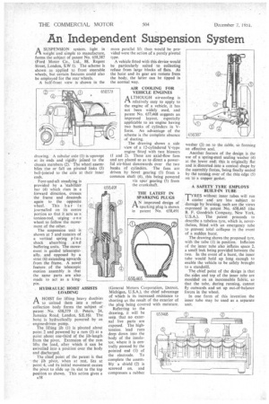
A half-front view is shown in the
drawing. A tubular axle (1) is upswept at its ends and rigidly joined to the be chassis members (2). The wheel assemblies rise or fall on pivoted links (3) ball-jointed to the axle at their inner ends. Fore-and-aft steadying is provided by a 'stabilizer bar (4) which rises in a forward direction, crosses the frame and descends again to the opposite wheel. This bar is journailed on its centre portion so that it acts as a torsion-rod, urging o e wheel to follow the movement of the other. The suspension unit is shown at 5 and .consists of a vertical spring plus shock absorbing and buffering units. The movement is guided telescopically, and opposed by a strut (6) extending upwards from the frame. A novel feature of the telescopic motion assembly is that the same parts are also made to act as a kingpin.
HYDRAULIC HOIST ASSISTS LOADING
A HOIST for lifting heavy dustbins to unload them into a refusecollection body forms the subject of patent No. 658,579 U. Peters, 24, Jamaica Road, London, S.E.I6). The heist is hydraulically powered by an engine-driven pump. The lifting jib (1) is pivoted about point 2 and powered by a ram (3) at a point about one-third of the jib-length from the pivot. Extension of the ram lifts the load, after which it can be swivelled into a position over the body and discharged. The chief point of the patent is that the jib pivot, when at rest, lies at point. 4, and its initial movement causes the pivot to slide up its slot to the top position as shown. This action gives a A38
moreparallel lift than would be pro vided were the action of a purely pivotal type.
A vehicle fitted with this device would be particularly suited to collecting refuse from large blocks of flats. As the hoist and its gear are remote from the body, the latter can be tipped in the normal way.
AIR COOLING FOR VEHICLE ENGINES
A LTHOUGH air-cooling is Pl. relatively easy to apply to the engine of a vehicle, it has not been widely used, and patent No. 657,468 suggests an improved layout, especially applicable to an engine having two banks of cylinders in Vform. An advantage of the scheme is the complete absence of ducting. The drawing shows a side view of a 12-cylindered V-type engine fitted with two blowers (1 and 2). These are axial-flow fans a
and are placed so as to direct powerful air-blast downwards over the two
cylinders. T
banks of cylinhe fans are driven by bevel gearing (3) from a
common shaft (4), this being poweredspur gearing (5) from viathe crankshaft.
(General Motors Corporation, Detroit, Michigan, U.S.A.), the chief advantage
of which is its increased resistance to shorting as the result of the exterior of the. plug being covered with moisture. Referring to the drawing, it will be seen. that no external live parts are exposed. The hightension lead runs deep down into the body of the insulator, where it is centrally pierced by the pointed end (l) of the electrode. To complete the assembly a shield (2) is screwed on. and compresses a rubber washer (3) on to the cable, so forming an effective seal..
Another feature of the design is the use of a spring-steel sealing washer (4) at the lower end; this is originally flat and is distorted into a conical shape by the assembly forces, being finally sealed by the turning over of the thin edge (5) on to a copper gasket.
A SAFETY TYRE EMPLOYS BUILT-IN TUBE. Twithout inner tubes will run I cooler and are less subject to damage by bruising; such are. the views expressed in patent No. 658,465 (the B. F. Goodrich Company, New York, U.S.A.). The patent proceeds to describe a tubeless tyre, which is, nevertheless, fitted with an emergency tube to prevent total collapse in the event
of a sudden burst. •
The drawing shows the proposed tyre, with the tube (I) in position. Inflation of the inner tube also inflates space 2, a small leak being provided between the two. In the event of a burst, the inner tube would hold up long enough to enable the vehicle to be safely brought to a standstill.
The chief point of the design is that the sides and top of the inner tube are moulded on an inextensible fabric, so that the tube, during running, cannot fly outwards and set up out-of-balance forces in the wheel. In one form of this invention the inner tube may be used as a separate unit.