


Experience Tells in the• Regal Mk. IV
Page 48
Page 49
Page 50
Page 51
If you've noticed an error in this article please click here to report it so we can fix it.
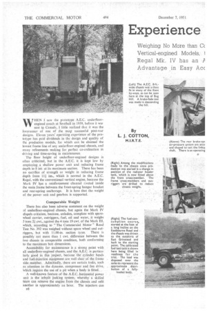
WHEN I saw the prototype A.E.C. underfloorengined coach at Southall in 1939, before it waF sent to Canada, I little realized that it was the forerunner of one of the mot successful post-war designs. Eleven years' operating experience of the prototype has paid dividends in the design and quality of the prod ucton models, for which can be claimed the lowest frame line of any underfloor-engined chassis, and many refinements making for perfect co-ordination in driving and time-saving in maintenance.
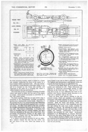
The floor height of underfloor-engined designs is often criticized, but in the A.E.C. it is kept low by employing a shallow power unit and reducing frame depth to 8 iris at its maximum section. There has been no sacrifice of strength or weight in reducing frame depth from 1 1 f ins., which is normal in the A.E.C. Regal, with the conventional vertical engine, because the Mark IV has a reinforcement channel riveted inside the main frame between the front-spring hangar bracket and rear-spring anchorage. It is here that the _weight of the power unit and gearbox is supported.
Comparable Weight There has also been adverse comment on the weight of underfloor-erigined chassis, but again the Mark IV dispels criticism, because, unladen, complete with sparewheel carrier, outriggers, fuel, oil and water, it weighs 5 tons 21; cwt., against the 4 tons 19 cwt. of the Mark III, which, according to "The Commercial Motor" Road Test No. 392 was weighed without spare wheel and outriggers, but with 11.00-in. section tyres. There is possibly not more than 1 cwt. difference between the two chassis in comparable condition, both conforming
to the maximum box dimensions. , Accessibility for maintenance is a strong point with all underfloor-engined chassis, and the A.E.C. is partictitarty good in this respect, because the cylinder heads and fuel-injection equipment are well clear of the frame side. member. Admittedly, there are certain tasks, such as attention to the dynamo, compressor and fan drive, Which require the use of a pit when a body is fitted. ,
A well-known feature of the A.E.C. horizontal power unit is the inbuilt jacking system, whereby a. skilled team can remove the engine from the chassis and refit another in approximately an hour. The injectors can
D8
. be taken out in live minutes, and the fuel-injection pump dismantled for inspection or testing in 3i minutes. ...
Minor modifications have been made since production was first started. For example, the radiator header tank has been moved, from the. side of the frame to a more conventional position over the front cross-member. Pilot injection, although beneficial in reducing noise and bearing loading. was detrimental to fuel economy, so it is now offered as an alternative to the conventional equipment, but was not fitted to the test chassis: A Simms fuel-injectlon pump and C.A.V. injectors, set to an opening pressure of 175 atmospheres, • Were supplied in the test vehicle.
The singie-cylindeled water-cooled compressor, built into the engine, has , been replaced by a larger, a ircooled unit of increased capacity (11 cubic ft. per minute), driven by shaft and belt from the front of the
crankshaft. The silencer on the coach .chassis is mounted transversely in the frame, 'behind the rear axle..
Promoting Turbulence
The characteristics of the A,E.C. 9.6-litre engine are well known. It employs an open toroidal combustion chamber and masked inlet_ valves, and develops 125 b.h.p. at 1.800 r.p.m. on the test bed, and 430 lb.-ft.
torque at 1,000 r.p.m. The timing-gear drive comprises a simple train of helical gears with a springloaded idler; there is no chain. The main casting is divided vertically at the crankshaft centre .line, the crankcase and cylinder bloct forming an integral cast
ing. The crankcase extension and sump are bolted in • it. Steel-shell white-metal-lined bearings are employed for the " top " half of the main bearings, and the " lower " shell and connecting-rod bearings are lined with lead-bronze.
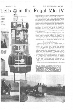
A.E.C.-Metalastik flexible mountings carry the engine, the front mounting bracket, which is bolted to a frame side member, supporting the front of the engine by a large bonded rubber-and-metal bush. The rear mounting comprises a large-diameter cross-tube, bolted at one end to a bracket on the frame side member and supported at the other by a swinging link which is rubber-bushed at the top and bottom.
The cross-tube carries a V-shaped mounting of bonded rubber and metal in which the rear end of the engine is housed. Fore-and-aft movement is restrained by a link with rubber bushes.
The fluid coupling, which has an open starter ring, is connected to the independently mounted pre-selective gearbox by a mechanically jointed shaft. Operation of the gearbox bus bar is by compressed air, thus dispensing with the relay of rods and levers required with a mechanical system. An offset worm drive to the axle completes the straight transmission line from the crankshaft to the rear axle. The worm is underslung. A 35-gallon fuel tank, or 45-gallon tank on overseas models, and spare wheel are mounted on the near side of the frame, thus preventing out-of-balance loading on the engine and transmission. Chassis built for bus service have the spare wheel behind the rear axle.
It is almost conventional practice to put an underfloor radiator behind the axle but the A.E.C. has the unit ahead of the axle, where the chance of its being fouled is less and air flow is probably improved. The radiator unit incorporates a cast shroud, which also supports the front bearing of an eight-bladed fan.
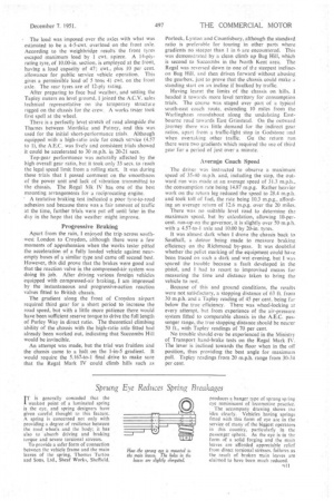
A feature of the Regal Mark IV is its smooth riding quality and resistance to roll. These refinements are achieved by employing equal-length springs of high deflection at the front and rear. They are 5 ft. 2 ins. long, have 54 ins. to 6 ins, deflection and work in conjunction with Newton Bennett shock absorbers at the front and a stabilizer unit at the rear.
There are three main delivery sections in the airpressure system, which now includes a two-cylindered compressor with ample capacity for door-gear operation in addition to the requirements of brake and gearbox actuation. Both the brake and bus-bar valves are incorporated in the reservoir, thus simplifying the pipe line and making the units more readily available for inspection or removal. By reducing the length of pipe line, air friction within the pipe and time delay in the system are reduced. Independent brake-operating cylinders are provided for each wheel. Air-pressure equipment is of Westinghouse or Clayton Dewandre manufacture, the latter being fitted to the test model.
The test chassis, loaded to slightly under 11 tons grass. was collected from Southall early one wet morning, and there was barely a minute throughout the day when the rain was not pouring.
The -load was imposed over the axles with what was estimated to be a 4-5-cwt. overload on the front axle. According to the weighbridge resultsthe front lyres escaped maximum load by I cwt.. apiece. A 14-plyrating tyre, of 10.00-in, section, is employed at the front, having a load capacity of 471 cwt., plus 10 per cent. allowance for public service vehicle operation. This gives a permissible load of 5 tons. 41 cwt. on the front axle. The rear tyres are of 12-ply rating.
After preparing to face bad weather, and setting the Tapley meters on level ground, I joined the A.C.V. sales technical representative on the temporary structure rigged on the chassis for the crew. A works tester took first spell at the wheel.
There is a perfectly level stretch of road alongside the Thames between Mortlake and Putney, and this was used for the initial short-performance trials. Although equipped with a high-ratio axle for coach service (4.57 to 1), the A.E.C. was lively and consistent trials showed it could be accelerated to 30 m.p.h. in 20-21 secs.
Top-gear performance was naturally affected by the high overall gear ratio, but it took only 33 sees. to reach the legal speed Limit from a rolling start. It was during these trials that I passed comment on the smoothness of the power unit and lack of vibration transmitted to the chassis. The Regal Mk IV has one of the best mounting arrangements for a reciprocating engine.
' A tentative braking test indicated a poor tyre-to-road adhesion and because there was a fair amthint of traffic at the time, further trials were put off until later in the day in the hope that the weather might improve.
Progressive Braking
Apart from the rain, I enjoyed the trip across southwest London to Croydon, although there were a few moments of apprehension when the works tester pitted the acceleration of a fully loaded vehicle against nearempty buses of a similar type and came off second best. However, this did prove that the brakes were good and that the reaction valve in the compressed-air system was doing its job. After driving various foreign vehicles equipped with compressed-air braking, I am impressed by the instantaneous and progressive-action reaction valves fitted to British chassis.
The gradient along the front of Croydon airport required third gear for a short period to increase the road speed, but with a little more patience there would have been sufficient reserve torque to drive the full length of Purley Way in direct ratio. The theoretical climbing ability of the chassis with the high-ratio axle fitted had already been worked out, indicating that Succombs Hill would be invincible.
An attempt was made, but the trial was fruitless and the chassis came to a halt on the 1-in-5 gradient. It would require the 5.167-to-1 final drive to make sure that the Regal Mark IV could climb hills such as Porlock, Lynton and Countisbury, although the standard ratio is preferable for touring in other parts where gradients no steeper than 1 in 6 are encountered. This was demonstrated by a clean climb up Bug Hill, which is second to Succornbs in the North Kent area The Regal was reversed down to one of the steepest inclines on Bug Hill, and then driven forward without abusing the gearbox, just to prove that the chassis could make a standing start on an incline if baulked by traffic.
Having learnt the limits of the chassis on hills, I headed it towards more level territory for consumption trials_ The course was staged over part of a typical south-east coach route, extending 10 miles from the Warlingham roundabout along the undulating Eastbourne road towards East Grinstead. On the outward journey there was little demand for the indirect gear ratios, apart from a traffic-light stop in Godstone and when overtaking other traffic, On the return run there were two gradients which required the use of third gear for a period of just over a minute.
Average Coach Speed
The driver was instructed to observe a maximum speed of 35-40 mph. and, including the stop, the outward run was made at an average speed of 31.3 m.p.h., the consumption rate being 14.87 m.p.g. Rather heavier work on the return leg reduced the speed to 28.4 m.p.h. and took toll of fuel, the rate being 10.3 m.p.g., affording an average return of 12.6 m.p.g. over the 20 miles.
There was no suitable level road to determine the. maximum speed, but by calculation, allowing 10-percent. run-up on the governor, it is slightly over 50 m.p.h. with a 4.57-to-1 axle and 10.00 by 20-in. tyres.
It was almost dark when 1 drove the chassis back to Southall, a detour being made to measure braking efficiency on the Richmond by-pass. It was doubtful whether the pellet marking of the equipment could have been traced on such a dark and wet evening, but I was spared the trouble because a fault developed in the pistol, and I had to resort to improvised means for measuring the time and distance taken to bring the vehicle to rest.
. Because of this and ground conditions, the results were not satisfactory, a stopping distance of 63 ft. from 30 m.p.h. and a Tapley reading of 45 percent. being far below the true efficiency. There was wheel-locking at every attempt, but from experience of the air-pressure system fitted to comparable chassis in the A.E.C. passenger range, the true stopping distance should be nearer 50 ft., with Tapley readings of 70 per cent.
No trouble should ever be experienced in the Ministry of Transport hand-brake tests on the Regal Mark IV. The lever is inclined towards the floor when in the oil position, thus providing the best angle for maximum pull. Tapley readings from 20 m.p.h. range from 30-34 per cent.