


AN Tyre Handling
Page 46
Page 47
If you've noticed an error in this article please click here to report it so we can fix it.
Made Easy
By P. G. TUCKER
Describing the Application of a Number of Tyre Manipulating Devices Which Turn an Irksome Job into one Requiring
Little Physical Effort
MUCH of the hard work normally associated with the removal and replacement of tyies and wheels has been eliminated by the evolution of a number of ingenious appliances.
The removal of a tractor tyre, for instance, can be an extremely heavy job, particularly in separating the bead from the rim. One way to avoid this trouble with all tyres is to treat the rim with a special, preparation before the tyre is mounted on it but, judging by the popularity of bead-moving appliances, this sensible precaution does not seem to be so widely adopted as it should be.
Tractor rims are usually of the welk. base type, so that once the bead has been freed from the rim, removal and replacement of the tyre resolve themselves into following the technique applicable to this type of rim.
Fortunately, there are several efficient bead-moving appliances available and although they may differ materially in design and method of application, they all serve to achieve the same result.
Bead-moving Tools The Dunlop device for tractor tyres .7onsiits of two hook-ended levers, one of which is pivoted to an adjustable hook-ended member that can bridge rims between 20 ins. and 40 ins, in diameter: The second lever, which is the operative One, is pivoted. at the loWer end of the first lever, the mechanical advantage thus obtained being such that little physical effort is required to separate the bead from the rini. -An accciOipanying illustration "clearly shows the Manner inwhich the appliance is Used.:
Operating on an entirely different principle is the U.T.S. bead knocker. This consists of a blunt .chisel-headed punch which slide § heavy sleeve. To operate the tool," the head of the pencil is first placed"in Position close up to the 'rim 'edge, .and.then the heavy sleeve is allowed to slide down to give a smart blow to the punch. The tool is, in effect, .a giant semi-automatic punch: • A36 Another shock-type appliance is the Weaver, which, by reason of its small size and low weight, can be used to loosen a tyre bead without removing the wheel from the vehicle. In the case of twin wheels, one wheel must be removed.
The Dunlop company makes a smaller version of its tractor tyre-bead mover, which covers rims from 13 ins. to 19 ins, in diameter.
One of the best-known types of tyre changer is the H.F. Robot, which is capable of dealing with all sizes of wheel and tyre. 'Weighing 2 cwt., it is intended for permanent installation, but the H.F.-ratchet tyre changer, an alternative design to the Robot, can be used anywhere without fixing.
In both cases the principle employed to remove a tyre is the same. There are two steel discs mounted on arms supported on an assembly which can be turned about a vertically mounted pillar. This pillar is threaded, as is the centre of the main assembly. When the main assembly is revolved in a clockwise directiot through the agency of a lever, the steel disci, which have previously been adjusted to bear up against the wheel rim, exert a steady pressure on the tyre as the centre assembly screws its way down the centre pillar.
The tractor tyre-bead separating tool made by the same concern is an appliance operated by a tommy bar. When the tommy bar is turned, a wedge is forced onto the tyre, the reaction forces being taken by a frame held again-st lift by a hooked bolt.
Although tools can be employed in fitting a tractor tyre, the usual practice is to " walk " them on. There is no doubt, however, that the auxiliary equipment for use on the HF. Robot tyre changer greatly simplifies the operation. With one bead in position on the rim, the assembly is placed on the changer with the loose bead uppermost.
The bead-replacing tool consists of a long lever which fits over a plain central
pillar. A roller on this lever is positioned so that when the lever is taken round the pillar, windlass-fashion, the roller forces the tyre bead over the
wheel rim. In all such operations a liberal application of soapy water to the surface of the bead Will be found of great assistance.
Removal and Replacement
For dealing with tyres on the lighter types of vehicle, there is the H.F. Master tool, the basis of which is a three-legged stand on which the wheel is securely held in the jaws of a self-centring chuck. Tyre removal and replacement are performed by using a master tyre lever and a roller which fits on the lever.
The removal and fitting of a tyre to, say, a four-piece wheel by entirely manual means is simplified if the correct procedure be adopted, but, in any event, four hands are better than two.
Having made certain that the inside walls of the cover are free from puncturing agents, insert the tube and slightly inflate it, remembering that too much air at this stage will increase the difficulty of mounting the tyre on the rim.
Next, place the flap in position between the tube and the bead, making certain that it lies snugly and evenly all round. After putting the first flange on, lower the tyre over the . wheel, noting that the valve is correctly positioned, The second flange may now be put on, followed by the locking ring with the split portion directly opposite to the valve. The square end of the ring should be forced into the gutter first, and with the tyre lever in the gutter and held well down, the lever should be driven round the rim with a hammer until the ring has been seated to within about I in, of the valve slot.
• Place a second lever at a point about 1 in. on the other side of the valve slot, then remove the first lever and continue to seat the ring for the full circumfer ence. Before fully inflating the tyre, make sure that the locking 'ring is correctly seated all round and, as a further precaution, see that the ring side of the wheel is away from the operator.
To remove the tyre, take out the valve core to allow all the air to escape from. the tube. Using both tyre levers, press down the right-hand one on the square end of the locking ring and. with the second lever, force the shaped end of the ring away from the gutter. Next, place the first lever underneath the locking ring at about 3 ins from the shaped end. The locking ring should then be removed from the gutter by prising upwards with the right-hand lever.
With the split ring released, the top flange is then loosened and removed. To withdraw the wheel, the whole assembly must be turned over.
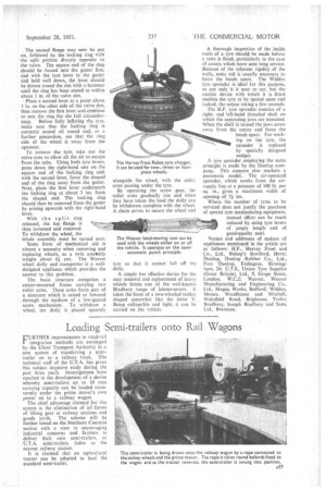
Some form of mechanical aid is almost a necessity when removing and replacing wheels, as a twin assembly .weighs about si cwt. The Weaver wheel dolly and transporter is a welldesigned appliance which provides the answer to this problem.
The basic structure comprises a • castor-mounted frame carrying two roller arms. These arms form part of a structure which is raised or lowered • through the medium of a low-geared screw mechanism. To. withdraw a wheel, the dolly is placed squarely alongside the wheel, with the roller arms passing under the tyre.
By operating the screw gear, the roller arms gradually rise and when they have taken the load the dolly can be withdrawn complete with the wheel. A chain serves to secure the wheel and
Lyre so that it cannot fall off the dolly.
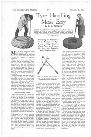
A simple but effective device for the easy removal and replacement of heavy wheels forms one of the well-known Bradbury range of labour-savers. It takes the form of a two-wheeled trolley shaped somewhat like the letter Y. Being collapsible and light, it can be carried on the vehicle. A thorough inspection of the inside walls of a tyre -shoulrj1 be made before a tube is fitted, particularly in the case of covers which have seen long service. Because of the inherent rigidity of the walls, some aid is usually necessary to force the beads apart. The Widdex tyre spreader is ideal for this purpose, as not only is it easy to use, but the ratchet device with which it is fitted enables the tyre to be spread open and locked, the action taking a few seconds.
• The H.F. tyre spreader consists of a rightand left-hahd threaded shaft on which the separating jaws are mounted. When the shaft N turned the jaws screw away from the centre and force the beads apart. For working on the tyre, the spreader is replaced by specially designed wedges.
A tyre spreader employing the same principle is made by the Dunlop company, This concern also markets a pneumatic model. The air-operated spreader, which works from the airsupply line at a pressure of 100 lb. per sq. in., gives a maximum width of opening of 7j ins.
Where the number of tyres to be serviced does not justify the purchase of special lyre manipulating equipment, manual effort can be much reduced by using tyre levers of ample length and of good-quality steel.
Names and addresses of makers of appliances mentioned in the article are as follows: H.F.,' Harvey Frost and Co., Ltd., Bishop's Stortford, Herts; Dunlop, Dunlop Rubber Co., Ltd., Fort Dunlop, Erdington, Birmingham, 24; U.T.S., Union Tyre Supplies (Great Britain), Ltd., 9, Grape Street, London, W.C.2; Weaver, Weaver Manufacturing and Engineering Co., Ltd., Magna Works, Bedford; Widdex, Messrs. Woodhouse and Mitchell, Wakefield Road, Brighouse, Yorks; Bradbury, Joseph Bradbury and Sons, Ltd., Braintree.