


Reduction Gear for Gas Turbine
Page 60
If you've noticed an error in this article please click here to report it so we can fix it.
THE application of a. gas turbine to road-vehicle propulsion forms the subject of patent No.. 628,201, which comes from J. Weaving and The Austin ,Motor Co., Ltd., both of Longbridge , Works,.'Birmingham.
As is well known,, a gas turbine 'generates a low torque at an extremely high speed, whereas a road vehicle demands a high torque at low speed, esPecially at starting, The chief point of the patent is a means for gearing down, and an hydraulic mechanism is used for the purpose.
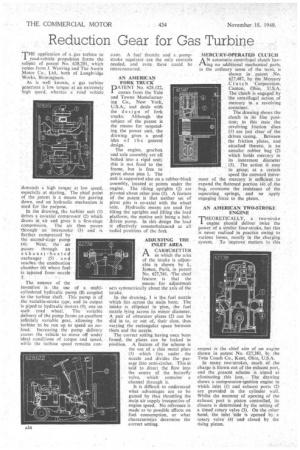
In the drawing, the turbine unit (1) "driVes a co-axial compressor" (2) which draws in air and giveSit a first-stage compression. The air then passes 'through' ad intereooler (3) and is further compressed by .
the second-stage pump 14). Next, the air -passes through an exhaust-heated exchanger (5) a n d reaches the combustion chamber (6) where fuel-, iS injected from nozzle
The essence of the
invention is the use of a multicylindered hydraulic pump (8) coupled to the turbine shaft. This pump is of the variable-stroke type, and its output Is piped to hydraulic motors (9), one on each road wheel.The variable ,delivery of the pump forms an excellent infinitely variable gear, allowing the turbine to be run up to speed on noload. Increasing the pump delivery causes the vehicle to. move off under ideal conditions of torque and speed, while the turbine speed remains con
stant. A fuel throttle and a pumpstroke regulator are the only controls needed, and even these could be interconnected.
AN AMERICA;4 FORK TRUCK PATENT No. 628.122, comes from the Yale and Towne Madufactur7 ing Co., New York, U.S.A., and deals with the design of fork trucks. Although the subject of the patent is the means for suspending the power unit, the drawing gives a good idea o f the general design.
The engine, gearbox and axle assembly are all bolted into a rigid unit; this is not fixed to the frame, but is free to pivot about pins 1. The unit is supported also on a rubber-block assembly, located at points under the engine. The tilting uprights (2) are pivoted about other pins (3). A feature of the patent is that neither set of pivot pins is, co-axial with the wheel axle. Hydraulic means are used for tilting the uprights and lifting the load platform, the motive unit being a beltdriven pump. In this design the load is' effectively counterbalanced at all radial positions of the fork ADJUSTING THE INLET AREA
A CARBURETTER in which the area of the intake is adjustable is shown by' L. Jenten, Paris, in patent No. 627,741. The chieffeature is that the
means for adjustment acts symmetrically about the axis of the intake.
In the drawing, 1 is the fuel nozzle which lies across the main bore: The intake is elliptical in 'plan, the fuel nozzle lying across its minor diameter. A pair of obturator plates (2) can be slid in to, or out of, their slots, thus varying the rectangular space between them and the nozzle.
The correct setting having once been found, the plates can be locked in position. A feature of the scheme is the use of a thin metal plate (3) which lies under the nozzle and divides the passage ihto semi-circles. This is said to direct the flow into the centre of the butterfly valve, which contains a channel through it.
It is difficult to understand what advantages are to be gained by thus throttling the main air supply irrespective of engine speed. No reference is made as to possible effects on fuel consumption, or what characteristics determine the correct setting. MERCURY-OPERATED CLUTCH
AN automatic centrifugal clutch having no additional mechanical parts. in the ordinary sense of the tern), is
shown in . patent .No. 627,487, by the Mercury Cl utch Corporation, Canton, Ohio, 1.J.S.A. The clutch is eng„aged by the centrifugal action of mercury in a revolving container.
The drawing shows the clutch in it gee position; in this state the revolving friction discs (1) are just clear of the driven casing. Between the friction plates, and attached thereto, is an annular rubber bag (2) which holds mercury in its innermost diameter (3). The action it easy to grasp; at a certain speed the outward movement of the mercury is sufficient to expand the flattened portion (4) of the bag, ,overcome the resistance of the separating springs, and so apply engaging force to the plates.
AN AMERICAN. TWO-STROKE ENGINE.
'THEORETICALLY, a two-stroke 1 engine should deliver twice the power of a similar four-stroke, but this is .never realized in practice owing to various losses, mostly in the charging system. To improve matters in this
respect is the chief aim of an engine shown in patent No. 627,381, by the Twin Coach Co., Kent, Ohio, U.S.A.
In many two-strokes, much of the charge is blown out of the exhaust port, and the present scheme is aimed at
eliminating this loss. The .drawing shows a compression-ignition engine in which inlet (1) and exhaust ports (2) are provided in the cylinder, wall. Whilst the moment of opening of the exhaust port is piston controlled, its closure is deterinined by the setting of a timed rotary valve (3). On the other hand, the inlet 'side is opened by a rotary valve' (4)' and closed by the rising piston.