


Concealed Brake Rods
Page 72
If you've noticed an error in this article please click here to report it so we can fix it.
A Relsurri of Recently Published Patent Specifications
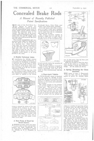
THE naine of the Ford Motor Co., Ltd., appears in patent No. 378,164, describing a system of brake rods and compensating beams which lie hidden within various tubular members forming the component parts of the chassis. The plan view of the accompanying group of illustrations shows the radius rods (10 and 17) within which the brake rods work to operate the front and rear brakes.
The internal arrangements and corn, pensating beam which are contained in the box shown at 20 are made plain in a sectional view. Other sectional views show the internal arrangements of the rods where they join the tubular front axle (13) and the radius rod (17) where it joins the rear axle (14). The kind of spring used in this arrangement would, appear to be lying parallel to the axles..
A ,Double Universal Joint.
IN specification No; 377,760, relating to a patent by Birger Ljungstrom, of Linnegatan 83, Stockholm, is described a universal joint of the kind in which two joints are provided to ensure more even rotation of the shafts when working at an angle, as in the case of frontwheel-driven vehicles.
Each joint is of the ring type, with its ring working within a:double casing. The simultaneous angular movement of each shaft in relation to the double easing is ensured by means of the cupand-ball device situated in the space between the ends of the shafts. An alternative to the cup-and-ball device is shown in an accompanying illustration, where two members are provided with circular grooves forming teeth, and so arranged that they will engage evenly when at an angle..
A New Form of Head for Wood Screws.
4, SIMPLE invention which may prove
of great value to those such as bodybuilders who make considerable use of wood screws is described in patent No. 377,538, by W. F. Flesselles, e50 Macdonald Street, Potts Point, near Sydney, New South Wales, Australia.
It is well known that when a screwdriver is used it often has a tendency to work sideways in the slot in the head, and in rapid work this is a hindrance and causes loss of time.
Tho present invention consists in forming a slight, dent on each side of the slot at the centre, so that a corresponding groove in the screwdriver may be held centra ly during the operation of . driving the screw home.
With suitable machinery it should be possible to form the dents in the head without appreciable extra cost, as it might be done simultaneously with the glotting.
A Four-track Vehicle.
A POUR-TRACK vehicle is described
in the patent No 377,790, of Leon Martinage, 46, Rue de CourceIles, Paris, which, it is claimed, will pass over such obstacles as tree trunks and moderately wide trenches.
The vehicle consists of two separate parts Pivoted tdgether at points 3 by
a third part. The pivots are central with each chain-bearing part, so that on. meeting an obstacle the front part can tilt, while the rear part can retain its grip by having the full length of its track incontact with the ground and
ten, by this means, help the front part to negotiate the obstacle.
Stops are provided to limit the movement of the parts to a straight line when crossing a trench, thus forming a bridge. All the tracks are driven.
A Spring Mounting for Closo Quarters.
THE names of John T. Thornycroft and Co., Ltd., and V. C. Burford appear in patent No. 377,928, which relates to a method of mounting springs in vehicles where the differential casing is set to. one side for the purpose of obtaining a low floor on passengercarrying vehicles. In snch cases it has, in the past, been found difficult to find room for a reasonably wide spring ; to provide this extra room is the main object of the present invention.
The spring (1) is mounted below the axle casing (5). and is supported on both sides by the pair of fiat members 0), these being held together by screws with sunken heads. These plates have slots in theth through which projections from the spring leaves can pass to, prevent movement lengthwise. A cap plate (6) is provided which can hold a rubber buffer: