


A Self-governing Injection Pump
Page 62
If you've noticed an error in this article please click here to report it so we can fix it.
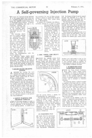
T0 make the injected charge diminish as the engine speed rises is the aim of a modified injection pump shown in patent No. 648,297, which comes from A. Pischinger, Graz, Austria. A known method of achieving this end is by elastically limiting the,
volume of fuel, enclosed in the . working space, and the patent shows an improved means for doing it.
The drawing shows part of a pump working on conventional lines, the discharge commencing when the suction port (I) is covered by the plunger, and terminating when the helical groove (2) meets the spill port (3). The essence of the scheme is the inclusion of a resilient capsule (4) the inner chamber of which (5) communicates with the suction gallery (6). In operation, higher engine speed develops higher pump pressure which then compresses the capsule, and so diminishes the charge by an amount equal to the extra volume thus created. This means that increase of speed cuts down the fuel supply, thus making the pump self-governing.
VARIABLE-RATIO BRAKING SYSTEM
AN1EANS for varying the ratio between the front and rear brakes of a vehicle is the subject of patent No. 648,307, which comes from B. Heller, Prague, Czechoslovakia.
The arrangement is too complex to describe in brief, but the basic principle of the scheme is that the retardation of the vehicle, caused by ordinary braking, swings an inertia weight which acts on the servo motor in such a way that the front brakes are increasingly loaded whilst the rear set are eased off slightly. Another feature of the patent is that the relative ratio can be manually preset by a driver's control to suit prevailing road conditions.
A SAFETY WARNING FOR DISABLED VEHICLES
ONE of the major dangers at night on the road is the stationary disabled vehicle, especially if the breakdown be in the lighting system. A useful warn
ing accessory for use in these circumstances is shown in patent No 647,865, by Joseph Lucas, Ltd„ Great King Street, Birmingham.
It consists of a foldable red reflector. normally encased in a cover to avoid damage during travelling. Referring to the drawing, a red prismatic reflecting surface (I), preferably of a distinctive outline, is normally housed in a casing (2) as shown in broken line. In use, the casing is • opened into position 3 so that it forms a stand for the reflector when placed on the road. The unit can be positioned some distance away from the breakdown so that adequate warning is given to approaching drivers.
A 'DISC WHEEL FOR HEAVY VEHICLES
PATENT No. 648,086 comes from Joseph Sankey and Sons, Ltd., Bilston, Staffs, and discloses a design intended mainly for the heavier types of vehicle. When such a wheel is pressed from sheet steel, it has been found to be almost impossible to form a dead flat surface for mating with the wheel drum,
and the patent shows a means for circumventing the requirement.
The drawing shows a fragment of the wheel in which 1 is the part that is bolted-up to the drum. Instead of attempting to form a flat face here, it is proposed to up-set small platforms (2) around the bolt holes. These platforms are easy to make in a common plane, so that no distortion is caused when the drum is bolted on.
AN INGENIOUS NUT
IT might often be convenient Ito use a nut on the inside of a tank or in similar circumstances in which the desired spot is completely inacces sible. For use in this respect. a nut is shown in patent No. 647,380, by Guest, Keen and Nettlefolds (Midlands)„ Ltd. Its feature is that it can be passed through the bolt-hole in a tank, for instance, and then expanded into an abutting position on the inside face.
The drawing shows the nut (I) in the loose state, in which it can freely pass through the hole, and is stopped only when a countersunk head (2) meets the edge of the hole. A special bolt-like tool is then screwed Into the nut. and tightened with some force.
This fractures the tapering body at its thinnest point (3) and draws it into the tubular part of the unit. This action expands the tubular part, which finally
doubles over and comes to rest on the inner wall, as shown at 4. A rigid abut is thus formed which is capable of withstanding the pull of the bolt proper.
The device is shown reversed.
A RUBBER-MOUNTED SUSPENSION SYSTEM
FROM the Twin Coach Company, Kent, Ohio, U.S.A., comes patent No. 648,432, in which is disclosed an improved type of suspension employing rubber as the resilient medium. The scheme is intended mainly for passenger coaches, and is claimed to eliminate vibration.
The drawing shows a typical example as. applied to the front axle of a vehicle. The axle carries a long metal tube (1) lined with rubber bushes to support the central rod (2). The latter unit carries arms (3) at its ends, and these are attached to the frame by shackles shown generally at 4. The shackles are, in effect, of the conventional type, but are provided with bonded-in rubber bushings on both pins.
A feature of the scheme is that the system is negatively pre-stressed to an extent such that when the vehicle is fully loaded the stress is reduced to zero. Metal torsion-rods may also be incorporated in the system, but these form no part of the present patent. •