


CENTRING FABRIC UNIVERSAL JOINTS
Page 74
If you've noticed an error in this article please click here to report it so we can fix it.
A Résumé of Recently Published Patent Specifications.
IN their specifidation No. 306,980, Morris Commercial Cars' Ltd., P. G. Rose and W. W. Hamill describe a means for centring universal joints of the flexible fabric type. The device consists of two plates of sheet metal which are stamped out into the form of three-armed members, eaeh with holes for the usual bolts which secure them to their spiders. To one of these members is attached a boss, whilst to the opposite one a ball is fixed, the boss and, ball forming the centring device.
The main point of the invention appears to lie in the fact that the sheet-metal members are pressed into the rubber of the disc during the process of manufacture.
Another Brake Booster.
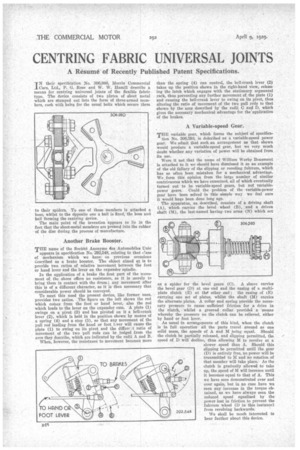
THE name of the Societe Anonyme des Automobiles Unic
appears in specification No. 292,548, relating to that class of mechanism which we have on previous occasions Cescribed as a brake booster. The object aimed at is to provide two ratios of relative movement between the foot or hand lever and the lever on the expander spindle.
In the application of a brake the first part of the movement of the shoes offers no resistance, as it is merely to bring them in contact with the drum; any movement after this is of a different character, as it is then necessary that. considerable power should be conveyed.
To meet this need the present device like former ones, provides two ratios. The figure on the left shows the rod which comes from the foot or hand lever, also the rod which leads to the lever on the expander cam. A plate (1) swings on a pivot (3) and has pivoted on it a bell-crank lever (2), which is held in the position shown by means of a spring (4) and a stop (5), so that any movement of the pull rod leading from the hand or foot 1..ver will cause the plate (1) to swing on its pivot and the differult ratio of movement of the two pull rods can be judged from the arcs they describe, which are indicated by the radii A and B. When, however, the resistance to movement becomes more
than the spring (4) can control, the bell-crank lever (2) takes up the position shown in the right-hand view, releasing the latch which engages with the stationary segmental rack, thus preventing any further movement of the plate (1) and causing the bell-crank lever to swing on its pivot, thus altering the ratio of movement of the two pull rods to that shown by the arcs described by the radii 0 and D. which gives the necessary mechanical advantage for thelapplication of the brakes.
A Variable-speed Gear.
THE variable gear, which forms the subject of specifica tion No. 306,593, is deRcribed as a variable-speed power gear. We admit that such an arrangement as that shown would produce a variable-speed gear, but we very much doubt whether any variation of power will be obtained from its use.
Were it not that the name of William Worby Beaumont is attached to it we should have dismissed it as an example of the old fallacy of the slipping or receding fulcrum, which has so often been mistaken for a mechanical advantage. We form this opinion from the large number of similar contrivances which we have examined, all of which eventually turned out to be variable-speed gears, but not variablepower gears. Could the problem of the variable-power gear have been solved in this simple way we feel sure it would hake been done long ago. The apparatus, as described, consists of a driving shaft (A), which carries the bevel wheel (B), and a driven shaft (M), the last-named having two arms (N) which act
as a spider for the bevel gears (C). A sleeve carries the bevel gear (D) at one end and the casing of a multiplate clutch (E) at the other end ; the casing of lE) carrying one set of plates, whilst the shaft (M) carries the alternate plates. A collar and spring provide the neeesr,ary pressure to cause sufficient friction for a drive in the clutch, whilst a grooved collar provida a means whereby the pressure on the clutch can be relieved, either by hand or foot lever.
As usual in arrangements of this kind, when the clutch is in full operation all the parts travel around as one solid mass, the speeds of A and M being equal. Should the clutch be partially released, and slipping permitted, the speed of D will decline, thus allowing M to revolve at a slower speed than A. Should this slipping be permitted until the gear (D) is entirely free, no power will be transmitted to M and no rotation of that member will take place. As the clutch is gradually allowed to take up, the speed of M will increase until it becomes equal to that of A. This we have seen demonstrated over and over again, but in no case have we seen any increase in the torque obtained, as we have always seen the reduced speed equalized by the power lost in friction to prevent the fulcrum wheel (D in this instance) from revolving backwards.
We shall be much interested to hear further about this device.