THE FLAT-EIGHT ENGINE and Its Possibilities
Page 58

Page 59

Page 60

If you've noticed an error in this article please click here to report it so we can fix it.
THE motor coach and motorbus have come to stay. This is certain, for the ever-increasing popularity of this branch of road transport is apparent on every route and in every town and city throughout the British Isles. Developments both in chassis and body design have been extraordinarily rapid of late and the question may fairly be asked, Has finality yet been reached? We would state most emphatically that it has not Progress may be slower in the future than in the past, but there seems to be no doubt whatever that designs will advance materially in the next few years.
Regarding the lines which developments may take there must, of course, be a certain amount of specula-lion as with every other sphere of industrial activity, but where any point of design may affect the user's pocket then it is fairly safe to venture suggestions as to how matters can be improved.
In this article it is proposed to deal with one aspect of the motor passenger-carrying industry (for it has now reached the stage when such a term as industry may be correctly applied), that is, the question of bodyspace culargement. Modern buses and coaches carry far more scats, and these afford a higher degree of comfort, than did the vehicles of a decade ago, largely due to the compacting of the engine and the introduction of forward control. There atill remains, however, room for improvement, for in quite a moderate-sized bus the power unit takes up a large amount of space, which, so far as 'pay load" is concerned, represents lost revenue to the operator.
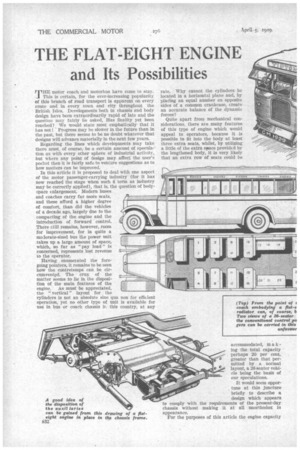
Having enumerated the foregoing pointers, it remains to be seen how the contretemps can be circumvented. The crux of the matter seems to lie in the disposition of the main features of the engine. As must be appreciated, the " vertical " layout for the cylinders is not an Absolute sine qua non for efficient operation, yet no other type of unit is available for use in bus or coach chassis IT this country, at any rate. Why cannot the cylinders be located in a horizontal plane and, by placing an equal number on opposite sides of a common crankcase, create an accurate balance of the dynamic forces?
Quite apart from mechanical considerations, there are many features of this type of engine which would appeal to operators, because it is possible to fit into the body at least three extra seats, whilst, by utilizing a little of the extra space provided by the lengthened body, it is very, likely that an extra row of seats could be
accommodated, mu a k ing the total capacity perhaps 20 per cent. greater than that permitted by a normal layout, a 26-seater vehicle being the basis of our speculations.
It would seem opportune at this juncture briefly to describe a design which appears to comply with the requirements of the . present-day chassis without making it at all unorthodox in appearance.
For the purposes of this article the engine capacity members to obtain a rigid mounting.
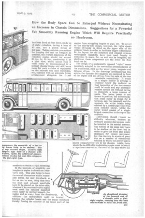
In the interests of simplicity our Imaginary engine is shown as a sidevalve unit. This also helps to keep the overall dimensions within reasonable limits, the only drawback, so far as can be seen, being that both the inlet and exhaust manifolds have to be placed on the valve side, whereas if an overhead-valve engine were used the exhaust manifold could easily be carried beneath the engine and so away from the floorboards. In addition, the carburetters could be located between the cylinder heads and the frame members; thereby freeing the exterior of the upper part of the has been fixed at four litres, made up of eight cylinders, having a bore of 80 mm. and a piston stroke of 100 mm. Taking suitable precautions for keeping the unit as compact as possible, the overall dimension of the complete engine should not exceed 30 ins. by 30 ins., considering it as a plan view, which means that it could easily be accommodated in a normal chassis frame and still leave room for such articles of equipment as the exhaust and inlet manifolds, etc., together with an adequate fixing arrangement alongside the fh.me engine from straggling lengths of pipe, etc. To revert to the side-by-side design, however, the valve chests would obviously be fitted on the upper side of the cylinder block in order to facilitate tappet adjustment. In the layout for the induction and exhaust systems rectangular manifolds have been used, largely to economize in space, for, as well can be imagined, the shallower these components are the lower the floor level can be.
The design of a horizontally opposed " eight " seems peculiarly adapted to the convenient accommodation of the auxiliaries, such as the water pump, magneto and dynamo drives. In the drawings accompanying this article the dynamo and magneto are mounted in front of the engine and are driven from the ends of the two camshafts respectively. It would be a simple matter to arrange a trapdoor below the radiator so that inspection of the instruments could be made and any necessary repairs carried out without having to dismantle a large number of parts. The water pump is not shown in position, but accommodation could easily be found for it between, say, the camshaft and the magneto, the water intake being effected by a double pipe (one from each cylinder block), whilst the outlet would consist of a singlebranch connection to the top of the radiator.
2 Lubrication should rresent no difficulty whatever, because an
29 ordinary pressure-fed system could be installed in the normal manner. zo The bottom of the sump may have to be shallow at the front end in order to give the front axle ample clearance for violent movement, 32 but this feature is standard practice on a number of commercial vehicles in which the power unit is placed comparatively low in the chassis. Again, there should be no difficulty in-obtaining ample room to install a capacious reservoir at the rear of the unit where the
Oil pump would presumably be disposed, the drive being effected in the normal manner through the medium of a pair of spiral spur gears of which one would be on the rear end of the camshaft and the other on a vertical shaft running to the pump at the lowest point of the sump.
Without making the engine unduly long, there would seem to be sufficient space for the crankshaft to be carried in five main bearings, which, considering the fact that all the dynamic forces are balanced for each pair of cylinders, should be ample for all practical Purposes. It is, of course, possible to compact• the crankshaft for each pair of cylinders by inclining the webs so that the connecting rods just clear the bosses of the main bearings and the webs of their, fellow throws. This arrangement also assists in reducing the horizontal couple between each pair of cylinders, which Is really desirable, but not so important as it would appear on the surface, because the engine, as a whole, Is balanced in this respect. The crankshaft, however, is relieved of a certain amount of undesirable stress.
T h e transmis• sion could be identical with that employed on any ordinary present day chassis. The crankcase would appear to be ideally suited to accommod ate a bell-housing for the dutch, and the gearbox could, of course, be carried either unit wise with the engine or in a separate mounting farther back. In the matter of control, again, no diffi culty should be experienced in coupling-up, because, actually, the ecnclitions imposed by the layout for the fiat engine are almost the same as those on any forwardcontrol vehicle.
So much for the general layout of the components. It would be advisable now to consider the performance of such an engine in practice. As was indicated in an article which appeared in an issue of The Commercial Motor dated January 15th, 1929, and was entitled "The Technical Aspects of the Multi-cylindered Engine," the power developed by an engine of given capacity increases (other things being equal) as the number of cylinders is increased, thus, when comparing
a four-cylindered engine with an eight-cylindered unit, it would be expected that the power output would be greater, and in practice this is borne out.
Summed up briefly, the main advantages to be gained by increasing the number of cylinders are, first, that the compression ratio can be increased without making the engine more liable to pink when pulling hard at low, speeds. This means higher efficiency and, there being equality in other directions, a greater power output, due to several reasons, one of which is that the jacket loss is reduced. Secondly, the valves can be larger in an " eight " than in a "four," or even a "six," if the total capacity of the cylinders and the bore-stroke ratio remain constant.
So far as actual power output is concerned, the " eight " scores on every count. Suppose, for instance, that a four-cylindered engine of four litres capacity develops a maximum power of 48 b.h.p. at 2,400 r.p.m., then the " eight " could attain 2,950 r.p.ra. without causing any drop in efficiency due to the cylinders being incompletely filled with gas on the induction strokes Without taking into account any increase in efficiency permitted by raising the compression ratio, etc., the eight cylin dered engine should develop about 58 b.h.p., which, of course, represents an increase of nearly 25 per cent. in actual rower output, an item of no mean importance.
It would be interesting to have the opinions of both manufacturers and users anent the suggestions we have outlined. The advantages to be gained by the horizontal layout for the cylinders seem to be so obvious that it is difficult to imagine any point upon which serious criticism could be made. The additional body space available is really much larger than would be thought at first, but reference to the seating diagrams which accompany this article shows quite clearly how the additional accommodation could be obtained in the manner suggested.
The controls of the flat eight should not be difficult to arrange as they differ little from standard practice.


