


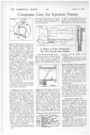
Composite Cam for Injection Pumps O W-ENGINE injection systems have two
Page 64
If you've noticed an error in this article please click here to report it so we can fix it.
requirements for. starting and slow running, a retarded timing and a high injection velocity. Whilst the latter can be obtained by the use of a steeply sloping cam, at high speeds this will cause noise and needless wear. A cam designed to reconcile these conflicting conditions is shown in patent No. 470,986 by the British ThomsonHouston Co., Ltd„ Crown HOuse, Aldwych, W.C.2, and others. '
The invention employs a cam of variable contour, theslope of which is lengthened or shortened automatically in accordance with the speed of the engine. Centrifugal force moves a partial cam (3) outwardly, with assistance from a weight (1), a spring return being employed. The drawing shows the device in the high-speed position in which the slope commences at point 2, thus spreading the lift over a wide angle. At slow speeds the rocking cam (3) is flush With the surface (shown dotted) • and the lift is then delayed until point 4.
The extra cam surface being added on the lifting side of the main cam results in the device acting also as an automatic-advance mechanism.
A Multi-purpose Municipal Vehicle.
AVEHICLE normally operating as a refuse collector, but capable, in emergencies, of adaptation to other purposes, forms. the subject of patent No. 470,879, by S. Allchurch, 2, Torrington Road, Portsmouth, and J. H. Sparshatt, 1, Old London Road, Hilsea, Portsmouth. The body has the usual, trap doors (1) for the admission of refuse, but these are capable of being made watertight by the use of special rubber gaskets; the body being otherwise sealed, liquid can then be earned. A power-driven pump , (3), which normally provides oil pressure for the operation of the tipping mechanism, can also be quickly converted to a pressure pump for spraying the liquid contents, a detachable union (2) forming the connection with the tank. Pipes are carried to all corners of the vehicle, where spraying heads or hose connections may be attached.
The vehicle is designed primarily for the use of municipal authorities which, foreseeing the possibility of air attack in war time, wish to possess a rapidly convertible plant for fire-fighting and gas decontamination.
Novel Injection-pump Movement.
order to obtain an abrupt starting and stopping motion of the injected fuel, it has often been proposed to make a pump utilizing only the midportion of the plunger stroke. Such a scheme forms the basis of patent No. 466,477 by L. H. Bellem, 34, rue de Chateaudun, Asnieres, Seine, France.'
An accompanying drawing shows the scheme applied to a combined pump and injector, the lower end being the spray nozzle, whilst the upper portion is moved by cam and rocker (not shown). The central plunger is surrounded by a spring-loaded sliding sleeve (3), which on its descent meets a cone (4) and, being arrested thereby, forms a fluid-tight seal. The central plunger continuing, injection takes place until an outer sliding sleeve (1) meets a ring of balls (2) ; the action of this is to press them inwards and so 'lift a cone attached to sleeve 3. This lifts the sleeve, breaks the fluidtight joint on 4 and thus terminates injection while the plunger is still descending.
• Output control is given by a rackand-pinion Lotion, the effect of which is to vary the diStance between Sleeire 1 and cone 4.
Improved Design of Slow-running Jet.
THAT the normal slow-running jet is 1 an inefficient atomizer, and leads to fuel wastage and lubricant dilution, is the statement made in patent No. 470,962 by A. Abramson, Lucemburska 24, Prague, Czechoslovakia. The inventor also remarks that liquid issuing from an orifice in a surface will always tend to adhere to that surface, and in the case of a carburetter will creep along the induction pipe and reach the cylinder in a still liquid state.
The remedy propose.] is snown in the accompanying drawing, and comprises a slight depression (1) immediately. above the slow-running orifice, in conjunction with a projecting baffle (2). Fuel leaving the edge of the orifice first flows into the depression, whence it is blown up the baffle and projected into the air stream.
Research into Cylinder Wear.
I NTERESTING statements regarding the wear of cylinders are made in patent No. 470,999 by the Standard Motor Co., Ltd., E. G. Grinham and L. H. Dawtrey, all of Canley, Coventry, who describe a cylinder liner of unusual dimensions. The inventors assert that most of the cylinder wear takes place in the region of the upper stationary point of the topmost piston ring, and it is, therefore, proposed to line only this part of the cylinder with a hardened sleeve.
A graph which accompanies the specification shows the result of the investigation and amply justifies the choice of a short liner. Other advantages are cheapness, ease of fitting and non-interference with water spaces: