


THE PANTHER ,EAPS INTO THE LIMELIGHT
Page 46
Page 47
Page 48
Page 49
If you've noticed an error in this article please click here to report it so we can fix it.
Perkins In troduc m.p.h. Goods Chu PassengerVehicle Lower than tha
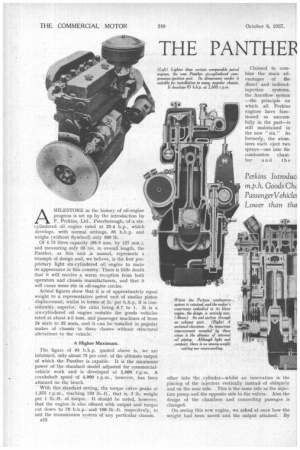
litre Power Unit for ,30Light and Medium-weight tt-to-power Ratio Markedly omparable Petrol Engine AMILESTONE in the history of oil-engine progress is set up by the introduction by F. Perkins, Ltd., Peterborough, of a sixcylindered oil engine rated at 29.4 h.p., which develops, with normal settings, 85 b.h.p. and weighs (without flywheel) only 580 lb.
Of 4.73 litres capacity (88.9 mm. by 127 mm.), and measuring only 33 ins, in overall length, the Panther, as this unit ,is named, represents a triumph of design and, we believe, is the first proprietary light six-cylindered oil engine to make its appearance in this country. There is little doubt that it will receive a warm reception from bothoperators and chassis manufacturers, and that it will cause some stir in oil-engine circles.
Actual figures show that it is of approximately equal weight to a representative petrol unit of similar piston displacement, whilst in terms of lb per b.h.p. it is considerably superior, the ratio being 6.7 to 1. It is a six-cylindered oil engine suitable for goods vehicles rated at about 4-5 tons, and passenger machines of from 24 seats to 32 seats, and it can be installed in popular makes of chassis in these classes without structural alterations to the vehicle.
A Higher Maximum.
The 'figure of 85 b.h.p. quoted above is, we are informed, only about 75 per cent, of the ultimate output of which the Panther is capable. It is the maximum power of the standard model adjusted for commercialvehicle work and is developed at 2,600 r.p.m. A crankshaft speed of 4,000 r.p.m., however, has been attained on the bench. • • With this standard setting, the torque curve peaks at 1,375 r.p.m., reaching 193 1b-ft., that is, 3 lb. weight per 1 Ib.-ft. of torque. It should be noted, however, that the engine is also offered with output and torque cut down to 70 b.h.p. and 160 lb.-ft. respectively, to suit the transmission system of any particular chassis.
812 Claimed to combine the main advantages of the direct and indirectinjection systems, the Aeroflow system —the principle on which all Perkins engines have functioned so successfully in the past—is still maintained in the new "six." As formerly, the atomizers each eject two sprays—one into the combustion chamber and the other into the ,cylinder—whilst an innovation is the placing of the injectors vertically, instead of obliquely and on the near side. This is the same side as the injection pump and the opposite side to the valves. Also the design of the chambers and connecting passages is changed'.
On seeing this new engine, we asked at once how the weight had been saved and the output attained. By
efficient design, came the reply, without recourse to the use of exceptionally light alloys, and by the improved Perkins combustion system. The elucidation of this comprehensive statement must lie, as in our case, in a detailed study of the make-up of the unit.
A single iron casting forms the cylinder block and top half of the crankcase, whilst the lower portion is a steel pressing. The head is a one-piece casting in iron, or, if preferred, in aluminium (at extra cost but 32 lb. lighter), and the timing-case body is of the latter metal, with a pressed-steel cover, having turned-up edges for stiffness.
Running in seven bearings, the crankshaft extends at the front, carrying a V-belt pulley and terminating in starting-handle dogs. The former drives the water pump and dynamo, whilst, within the case, a Reynolds Triplex chain runs the C.A.V.-Bosch injection pump and the high camshaft A tensioner, of the same make as the chain, is provided, whilst a compressed-fibre pad
fixed to the case steadies the chain on its longest run.
Although high-mounted, the water pump draws cool water from the bottom of the radiator, and discharges into an external pipe feeding the cylinder-head hot spots. Thence the water passes through the head, via a thermostat, back to the radiator, circulation in the cylinder jackets being by thermo-siphon. Efficient but not excessive cooling is thus ensured. On the offside is the dynamo, supported on an adjustable swinging link, and roughly in line with it at the back is the starter.
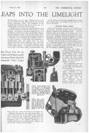
Pneumatic Engine Control.
Control of the engine is by the C.A.V.-Bosch pneumatic system. There is a throttle valve in the air intake, directly coupled to the accelerator pedal. From the induction pipe, at a point on the engine side of the valve, a tube runs to a chamber on the end of the injection pump. Forming a wall of this chamber is a leather /diaphragm, the centre of which is linked to the pump rack rod, by which the fuel metering is regulated.
Normally, the rod is held in the full.quantity position by a compressior. spring, but so soon as a depression is created, by the engine in the induction pipe, the diaphragm overcomes the spring pressure and cuts down the fuel supply by pulling the rack rod.
Obviously, the degree of vacuum depends primarily on the position of the pedal-controlled throttle valve, whilst the dimensions of the venturi, in which the valve works, govern the -unit for maximum speed, and the tick-over is similarly controlled.
This arrangement eliminates a centrifugal governor, thus saving weight and simplifying the mechanism.
A most ingenious system of engine ventilation is employed, which is provisionally patented. From each side of the air-intake, valve two vacuum pipes are led. In both, obviously, negative pressures obtain, but these pressures differ, and the pipes are so positioned that the difference is approximately constant at all speeds and loads.
The vacuum in one is about half an inch of water greater than in the other, so that if the two pipes are in communication with each other their contents circulate. Clean air is drawn by one pipe from atmosphere via the A.C. oil-damped cleaner on the main air intake. This is fed to the valve-gear chamber, passes thence downwards to the crankcase, through passages in the castings, and departs from the oil filler, to which the other pipe is connected, passing thence to the induction pipe and into the cylinders: We looked into this pipe while the engine was running on the test bench, and observed the fumes rising and being conducted away, their flow being hardly effected by changes of throttle opening made during our investigations. Oil mist is retained by a gauze.
Whilst aiding cool running, this ventilation militates against sludge formation, the major part of the fumes being water vapour, which otherwise would condense and deteriorate the oil. A test made at our request indicated that their oil content was nil.
On the same occasion we witnessed a test during which 91.5 b.h.p, was developed against a Heenan and Fronde water brake at 2,600 r.p.m., and, on a second test, about 80 per cent. of this output, at 2,000 r.p.m., corresponding with a cruising speed under typical conditions. Smoke from the exhaust was just discernible.
Then the engine was deliberately stalled down to 240 r.p.m. at full throttle, but it exhibited no signs of distress despite this definitely abusive treatment, the exhaust becoming slightly more smoky. There was little to distinguish the noise at maximum r.p.m. from that at 2,000 r.p.m., nor was there material increase in sound from no load to full load at the low crankshaft speed. During these tests a 60-lb. flywheel—about the normal weight—was employed. The compression ratio is 15.8 to 1.
Reverting to our description of the unit, a feature of the balanced crankshaft is that each journal has duplicated oilwaya..Two drillings run from each main to the crank-pins on both sides of it.
The pins and main journals, respectively, are of 21ins. and 21 ins, diameter, and both are Tocco electrically hardened. Lead-bronze is employed for the heavily loaded halves of both main and big-end bearings, white metal being used for the lower halves of the former and.
s14
upper halves of the latter. These bearings are steel backed,
Each main is carried on a sturdy bridge (the term seems a misnomer in that it has an unperforated web) and has a 40-ton pressed-steel cap located by thimble dowels and secured by A-in. nickel-chrome setscrews locked with tab washers. It is of note that the big-ends
are interchangeable with those of the Leopard and Wolf engines, and, in this connection, the materials and dimensions of all running parts are as on these two wellproved models, Of B.H.B. make, the pistons have shallow specially shaped recesses in the crowns which blend with the contours of the pre Combustion chamber throats. • They carry three pressure and two scraper rings and have large floating hollow gudgeon pins retained by circlips. Interchangeable, except for the camshaft, the valve gear follows standard design, its outstanding feature being the lightness of the reciprocating parts, the weight of which, due to the design, is little more than in the case of an overhead-camshaft engine. The layout is clearly shown on the preceding pages.
A departure from previous practice is found in the use of valves of different sizes. The inlet and exhaust valves, for both of which silicon-chrome steel is used, are those of the Leopard and Wolf engines respectively, and their ports 1 13-32 ins. and 1* ins, in diameter. Inserted seats are used only in the aluminium heads.
The new position of the combustion chambers allows bigger core spaces and better cooling, whilst the vertical injectors remove the need for any but square machining. Instead of being cylindrical, the chambers are now spherical, and an important point is that they are internally machined. This ensures precision of shape and equality of size. One half of each chamber is water cooled and the other is a nickel-steel cap secured
by three il-in. studs, spigoted and jointing on a plain copper ring. Of large diameter at the bottom, the connecting throat between cylinder and chamber is venturi shape and bends from vertical to horizontal, entering the spherical cell at a tangent. The atomizer nozzle discharges two sprays, one down the neck and the other tangentially into the chamber.
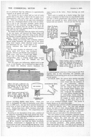
The head is secured by -75-in. studs, there being, in effect, five for each cylinder. An ordinary C. and A. gasket forms the joint. A notable detail is that all bosses interfering with air passages are streamlined. An accompanying drawing shows, in section, the water pump. Interesting features include the floating Bakelite impeller, which is impervious to the effects of boiling water, and which is extremely strong; the gland seal formed by the cast-iron insert bearing against the impellers; the brass pad, held up by a phosphor-bronze fiat spring and forming a thrust bearing at the other end, and the semi-floating spindle, carrying the drive from the independently supported pulley. With regard to the lubrication system, a skew gear on the injection-pump drive transmits rotation to a short shaft (having a dog at each end, permitting a small amount of malalignment), which, in turn, drives a submerged gear pump. This draws, via the only internal pipe, through a coarse filter and discharges through passages formed in the pump and crankcase castings to an external Tecalemit fabric-type filter. Then lubricant flows through a cast-in pipe to the mains, front camshaft bearing and locker gear. Ducts carry it to the bath which feeds the pump drive. To prevent escape of oil in the event of the gauge pipe fracturing, a no-loss ball valve is incorporated in the union of this tube with the main gallery_ While at the Perkins works we had a run in a Studebaker car in which the Panther had been installed. Incidentally, the conversion necessitated no enlargement of the space occupied by the original petrol unit. We were much impressed by its performance, particularly in respect of silence, lack of vibration and flexibility. Except for a trace of " Diesel " noise at tick-over speeds. it would be hard for one unaware of the presence of an oil engine to detect it. Pulling a 4i-to-I gear and a gross weight of 2 tons, the engine propelled the car smoothly down to about 9 m.p.h. From that speed, sudden full pressure on the pedal resulted in powerful and steady acceleration, with only momentary hesitation and absolutely no signs of distress, to. 65 This experiment was actually made up a 1-in-10 gradient. Our comment was that the hill might not have been-there I To give an idea of the price at which this engine is offered, we understand that in the case of the conversion of a new chassis from petrol to oil, F. Perkins, Ltd., is prepared to install the Panther, exchanging it for the original unit, for under £200.