


Abridgments of Interesting Patent Specifications.
Page 26
If you've noticed an error in this article please click here to report it so we can fix it.
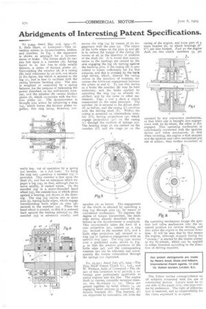
No 9,994, dated May 2nd, 1904.—II. S. Hele Shaw, of Liverpool.—This invention relates to dynamometers, brakes, and clutches. In Fig. I the apparatus is shown as arranged for a dynamometer or brake. The driven shaft (S) carries fast upon it a member (A), having keyed to it, but free to slide axially thereon, a series of friction plates (a). Surrounding the member (A) is a casing (B), held stationary by an arm, not shown in the figure, but which is secured to the lug (r), and is free to oscillate with the casing between banking pins. The arm is weighted or controlled by a spring balance, for the purpose of measuring the power absorbed, in the well-known manner, and the member (B) carries friction plates (b), which co-operate with the friction plates (a). The dynamometer is brought into action by advancing a ring (x41, which forces the friction plates together, this ring being, however, nor
mally kep. out of operation by a spring (22) mounte on a rod (22a). To bring the ring into ,,peration a member (23) is provided. This member is free upon the shaft (S), and has an exteasion which engages a lug (24), so that, although free to move axially, it cannot rotate. On the member (23) is a screw-threaded hand wheel (25), the outside face of which abuts against a bearing, not shown in the drawing. The ring (14) carries two or more pins (5), having knife edges, which engage corresponding knife edges on pins (913) secured to the member (23). When the hand wheel is rotated, so that it is screwed back against the bearing referred to, the member (23) is advanced axially, and
moves the ring (14) by means of its engagement with the pins (5). The object of the knife edges on the pins (5 and 913) is to reduce the torque if the casing (B) moves at all in the direction of rotation of the shaft (S). It is found that inaccuracies in the readings are caused by the arm engaging the lug (A) moving against the banking pins, if the casing (B) is per. rnitted to rotate sufficiently far for thit purpose, and this is avoided by the knift edge device, which, directly the casing moves in the direction of rotation, decreases the frictional engagement between the plates (a and b). To use this device as a brake the member (B) may be held stationary, and the brake applied by operating the ring (141 as already described, and by the same or other mechanism. Figs. 2 and 3 show a clutch constructed on the same principle. The member (A) is secured to the driven shaft (S) as before, and the casing (Cl revolves with the driving shaft (T). Within the casing is mounted an intermediate member (Cl), having projections (31) which engage projections (31') on the casing (C) through the medium of springs (12). The braking rings (b) are carried on the member (Cl) and the rings (a) on the member (A) as before The engagement of the clutch is effected by operating a ring (14) through pins (5), by means of convenient mechanism. To regulate the degree of torque transmitted, the knife edge device already described with reference to the dynamometer is employed. Thisconveniently takes the form of a cam projection (9c), carried on a ring (32, secured to the member (Cl), and a knife edge projection (9d) secured to a ring (33) in operatiqo engagement with an exterior ring (33a) The ring (33a) moves over a graduated scale, shown in Fig. 3, so that the relative positions of the knife edge (9d) and the corresponding member (9c) can be adjusted, and consequently the torque transmitted through the springs (12) regulated.
No. 15,352; dated July 9th, 1904.—The Hele Shaw l'atent Clutch Co., Ltd., and W. Wallace, both of Liverpool.—The ob. ject of this invention is to provide a reversing gear particularly applicable to petrol engines and the like. The engine shaft (2) carries, rotatably mounted thereon, two fly-wheels (t, xa). These are geared together by bevel wheels (4, 4a) engaging bevel pinions (5) carried by stationary brackets (6'). The brackets (6') are supported by extensions (18) from the
casing of the engine, and form part of a main bracket (6), in which bearings (6" 61") are also formed. Fast on the engine shaft are two clutch members (3, 3a) operated by any convenient mechanism, so that when one is brought into engagement with its fly-wheel, the other is disengaged. This operating mechanism is conveniently connected with the ignition device and valve mechanism, so that when reversing, the engine is first stopped and the ignition and valve mechanism put out of action; then further movement of the cperating mechanism hr ngs the ignition and valve mechanism into the required position for reverse driving, and also starts the engine in the reverse direction. It will be seen that by this means the engine, although stopped during the "reverse," is started by the kinetic energy in the fly-wheels, which can be applied in either direction according to the direction of driving required.
The Editor invites correspondence on all subjects connected with the use of commercial motors. Letters must be on one side of the paper only, and type-written by preference. The right of abbreviation is reserved, and no responsibility for the views expressed is accepted.