Patents Completed.
Page 20

If you've noticed an error in this article please click here to report it so we can fix it.
Dunlop and Clarkson Wheels. Austin Piston Construction.
Copies of complete specifications of the patents published on this page can be obtained from the Sales Branch, Patent Office, Holborn, W.C., at the cost of sixpence for each specification,
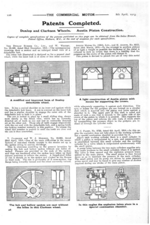
THE DUNLOP RUBBER CO., LTD., and W. WRIGHT, No. 29,540, dated 22nd December, 1913.—The accompanying drawings show a .sestion and an enlarged detail view of a detachable hub.
The outer hub illustrated is designed as for a pressed steel wheel, while the inner hub is of more or less usual construe
tion. It has a conical shoulder at its inner end against which the detachable hub hears. A nut is screwed on the inner hub and has a similar shoulder to engage the outer side of the detachable hub to hold it in place. The nut is locked in place by a small sliding ring, shown most clearly in the detail view, which has an inwardly directed set of teeth at one end and an outwardly directed set at the other end. These sets of teeth engage respectively with the nut and with the detachable hub, and a spring holds the locking member normally in this position. To release the wheel this member is pushed in until the teeth are clear and the nut is then unscrewed.
T. CLARKSON and W. J. Morersoe, No. 10,068, dated 23rd April, 1914.—One of the main difficulties in the manufacture of cast-steel wheels consists in the strains set up in the spokes owing to uneven shrinkage.
This is overcome according to the present invention by casting the hub and hollow spokes without any felloe attached. Flanges are provided on the ends of the spokes, and they are machined after the spokes have taken up their natural positions to relieve the strains. A forged-steel felloe or rim is shrunk on to the spokes and riveted to the flanges on their ends. The rim is preferably of Z cross-section, one flange being inwardly turned and the ether outwardly earned.
AUSTIN MOTOR CO. (1914/, LTD., and H. AUSTIN, No. 6015, dated 10th March, 1914.—In the attempt to produce pistons of as light a weight RS possible the thickness of the metal is reduced to such an extent that there is a liability that the pressure on the crown of the piston will distort it.
This piston is devised to permit the use of very thin metal while adequately supporting it against such distortion. The eyes or bosses for the gudgeon pm are formed on a circular shell which is screwed into the piston and butts against a shoulder in it. The upper part of this shell is coned and made of such a size that it extends to the under side of the crown of the piston to which it is secured. This supports the top of the piston and relieves the side walls of much strain by transmitting the pressure -direct to the gudgeon pin instead of through the cylinder walls.
S. C. Pacer, No. 8720, dated 6th April, 1914.—In this engine the explosion does not take place in the working cylinder but a special combustion chamber is provided for it.
Above each working cylinder there is a small cylinder in whia a piston is reciprocated by a cam, and communication is established between this small cylinder and the working cylinder by a valve which is reciprocated synchronously with the small piston.
A pump lying between the two main cylinders supplies mixture under pressure to the small cylinders where it is ignited. The valve is then opened and the explosion pressure transmitted to the main piston. The small piston is then forced down so as to maintain the pressure in the main cylinder. The small piston and its pump are driven by some separate prime mover and may be timed to give any number of strokes required during one stroke of the main piston.


