


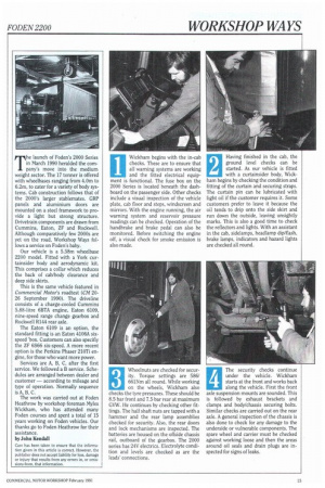
T he launch of Foden's 2000 Series in March 1990 heralded
Page 99
Page 100
Page 101
Page 102
If you've noticed an error in this article please click here to report it so we can fix it.
the company's move into the medium weight sector. The 17 tonner is offered with wheelbases ranging from 4.0m to 6.2m, to cater for a variety of body systems. Cab construction follows that of the 2000's larger stablemates. GRP panels and aluminium doors are mounted on a steel framework to provide a light but strong structure. Drivetrain components are drawn from Cummins, Eaton, ZF and Rockwell. Although comparatively few 2000s are yet on the road, Workshop Ways follows a service on Foden's baby.
Our vehicle is a 5.58m wheelbase 2200 model. Fitted with a York curtainsider body and aerodynamic kit. This comprises a collar which reduces the back of cab/body clearance and deep side skirts.
This is the same vehicle featured in Commercial Motor's roadtest (CM 2026 September 1990). The driveline consists of a charge-cooled Cummins 5.88-litre 6BTA engine, Eaton 6109, nine-speed range change gearbox and Rockwell R144 rear axle.
The Eaton 6109 is an option, the standard fitting is an Eaton 4106A sixspeed 'box. Customers can also specifiy the ZF 6S66 six-speed. A more recent option is the Perkins Phaser 210Ti engine, for those who want more power.
Services are A, B, C, after the first service. We followed a B service. Schedules are arranged between dealer and customer — according to mileage and type of operation. Normally sequence is A, B, C.
The work was carried out at Foden Heathrow by workshop foreman Myles Wickham, who has attended many Foden courses and spent a total of 15 years working on Foden vehicles. Our thanks go to Focien Heathrow for their assistance.
by John Kendall
Care has been taken to ensure that the information given in this article is correct. However, the publisher does not accept liability for loss, damage or injury that results from any errors in, or omissions from, that information.
Wickham begins with the in-cab checks. These are to ensure that all warning systems are working and the fitted electrical equipment is functional. The fuse box on the 2000 Series is located beneath the dashboard on the passenger side. Other checks include a visual inspection of the vehicle plate, cab floor and steps, windscreen and mirrors. With the engine running, the air warning system and reservoir pressure readings can he checked. Operation of the handbrake and brake pedal can also be monitored. Before switching the engine off, a visual check for smoke emission is also made.
1
Having finished in the cab, the ground level checks can be started. As our vehicle is fitted with a curtainsider body, Wickham begins by checking the condition and fitting of the curtain and securing straps. The curtain pin can be lubricated with Light oil if the customer requires it. Some customers prefer to leave it because the oil tends to drip onto the side skirt and run down the outside, leaving unsightly marks. This is also a good time to check the reflectors and lights. With an assistant in the cab, sidelamps, headlamp dip/flash, brake lamps, indicators and hazard lights are checked all round.
Wheelnuts are checked for security. Torque settings are 586/ 661Nm all round. While working on the wheels, Wickham also checks the tyre pressures. These should be 8.5 bar front and 7.5 bar rear at maximum GVW. He continues by checking other fittings. The half shaft nuts are tapped with a hammer and the rear lamp assemblies checked for security. Also, the rear doors and lock mechanisms are inspected. The batteries are housed on the offside chassis rail, outboard of the gearbox. The 2000 series has 24V electrics. Electrolyte condition and levels are checked as are the leads' connections.
3
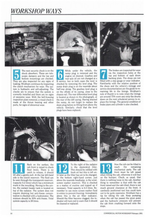
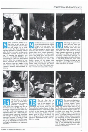
The security checks continue under the vehicle. Wickham starts at the front and works back along the vehicle. First the front axle suspension mounts are sounded. This is followed by exhaust brackets and clamps and body/chassis securing bolts. Similar checks are carried out on the rear axle. A general inspection of the chassis is also done to check for any damage to the underside or vulnerable components. The spare wheel and carrier must be checked against working loose and then the areas around oil seals and drain plugs are inspected for signs of leaks. The next security check is on the shock absorbers. These are telescopic dampers and the top and bottom mountings are checked. They are also inspected for any signs of leaking. Wickham continues by inspecting the clutch mechanism for wear. The system is hydraulic and self-adjusting. The checks are to ensure that the system is correctly installed and there are no signs of excessive wear. With the bell-housing inspection plate removed, a visual check is made of the thrust bearing and other parts, for signs of abnormal wear. While under the vehicle, the sump plug is removed and the engine oil drained. Gearbox and rear axle oil are not changed at a B service, but in both cases the level is checked by removing the level plug. The sump drain plug is on the nearside about half-way along. The gearbox level plug is on the offside of its casing, close to the chassis rail. The rear differential level plug is located as shown in the photograph, at the rear of the duff casing. Having drained the sump, do not forget to replace the drain plug before re-filling from above the vehicle. Similarly, check that the level plugs have been replaced. The brakes are inspected for wear via the inspection holes at the top and bottom of each drum backing plate. The shoes are not fitted with a step gauge or wear indicator. Familiarity with the relative position of the shoes and the vehicle's mileage and service documentation are the guide to remaining life in the linings. Wickham's rule of thumb is to note when the linings are around 75% worn and strip the drums down on the next scheduled service to replace the linings. The general condition of brake pipes and cylinder is also checked. Slack adjustment is taken up on the brakes at each service. It is very important to remember that on this vehicle, as on other Foden models, the slack adjusters are threaded differently on the front and rear axles. On the front, slack is taken up by turning the adjusters clockwise, on the rear by turning the adjusters anticlockwise. According to Wickham, it is not unusual for a vehicle to be brought in after the driver has complained of poor brakes. Inspection then shows that the rear adjusters have been slacked off in error because they have been turned clockwise, rendering the rear brakes ineffective. Careful attention should be paid to the load sensing valve and the linkage to the rear axle. First, check for free operation of the valve itself by moving the sensing lever manually. Then check the condition of the flexible parts of the linkage. Apparently, there is a tendency for the valve to stick after a long period of use, due to its location under the vehicle, where it is vulnerable to dirt. Faults can also occur if the flexible sections of the linkage have perished. In that case, the linkage may distort under load causing only partial operation of the valve. If the valve is sticking it will also tend to distort the linkage. Checking the play in the track-rod ends needs two people; one to turn the steering wheel while the other looks for excess movement in the joint from below the vehicle. Checking wheel alignment should not be necessary until a C service. Other final checks below the vehicle can be carried out now. This includes draining the air tanks, which can be done from ground level but is easier from below. Wickham also looks at each end of the cylindrical fuel tank for leaks where they join to the cylinder.
10 11
Back on the surface, the cab front is raised to check fluid levels. There is no catch to release, it should lift after a gentle pull. At the top left-hand side is the clutch reservoir. The fluid can be seen through the transparent reservoir, (capacity 0.2 litres) which has a minimum mark in the moulding. Moving to the centre, the coolant header tank is located on top of the radiator. The system does not require draining but anti-freeze concentration is checked with a hydrometer. The mixture should be 50% anti-freeze. Total system capacity is 38 litres. To the right of the radiator is the dipstick/oil filler. This should be refilled with fresh oil but this is left until later as the filter has yet to be changed. In the bottom right-hand corner, just above the nearside headlamp, is the windscreen washer reservoir. This is checked as a matter of routine and topped up if necessary. Total capacity is 6.5 litres. Remember to use more screen washer fluid in winter to prevent freezing. Immediately above this is the air filter indicator. Should the filter become clogged, the indicator will turn red to warn that it should be cleaned or replaced.
12
Now the cab can be tilted to
13
reach the remaining mechanical parts. The cab front must be left raised when tilting the cab, otherwise it will foul on the bumper. Check, as usual, that there is nothing loose in the cab. Another thing to remember, is that with the cab front raised and the cab tilted, there is not much ground clearance at the front. A carelessly positioned tool box could turn out to be quite expensive. Wickham has a tip for tilting the cab. Keep pumping when the cab has passed the pivot point and the hydraulic pressure will prevent the cab from crashing forward onto the stops. The first thing to check is the front air brake lines. These should not cause any problems normally. If either of the front cylinders have been replaced and incorrectly fitted, there is a danger that the pipes will foul on the front wheel, The problem is only apparent with the wheels on full lock. Consequently it is not easy to spot. Inspect the pipes carefully for signs of chafing, then bend the pipes over as shown to check the clearance between pipe and wheel. The clearance in the photograph is as it should be, anything less should give rise to a careful inspection.
14
The air filter box is mounted on top of the engine on the nearside. The element is withdrawn by unscrewing the knurled wheel on the front end of the housing. Inspect the filter element which should not need replacing on the B service. Reverse blow it with an air line if necessary. Wickham advises against trying to clean it by banging the end on the ground. This causes internal damage to the element which is not visible from outside.
15
The power steering fluid reservoir is mounted just behind the radiator. The replacement element filter is locked into position under the filler cap, but should not need replacement until a C service. The fluid is changed and the system bled at the same time. The power steering pump is located on the opposite side of the engine and should be checked for any signs of leakage. It has a test point for connection to a fluid pressure meter. Hoses should be checked for signs of perishing and leaking at joints. The fluid level in the reservoir must be checked with the engine running. Capacity is between 2.5 and 3.0 litres.
16
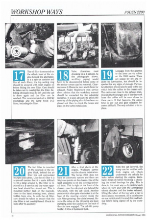
The oil filter is mounted on the offside front of the engine behind the alternator. It is a spin-on canister and like all such filters, the top sealing ring should be smeared with fresh engine oil before fitting the new filter. Care should be taken not to overtighten the filter, Refilling obviously must be left until the cab is down again and the filler can be reached. The recommended oil is 16W/40 multigrade and the sump holds 14.3 litres, including the filter.
17 18
Valve clearances need checking on a B service. As the photograph shows, ancilliary piping would have to be disconnected before some of the rocker covers can be removed. Clearances are 0.25mm for inlet and 0.5mm for exhaust. Foden Heathrow's own service sheet advises that the workshop manual should be consulted for the adjusting sequence. It is also advisable to check the security of the piping after it has been replaced and then to check the hoses and pipes on the turbo installation.
19
Linkages from the gearbox to the lever are via cables on the 2000 series. These are sealed for life and require no lubrication, but should be inspected for any signs of damage. Particular attention should also be paid to the ties which hold the cables to the chassis rail. The cables run close to the exhaust manifold and turbocharger and if the ties work loose the cables will be even closer to these parts. If that happens, the cables tend to dry out and gear selection becomes difficult. The only solution is to replace.
The fuel filter is mounted on the nearside of the engine block, behind the air filter box and surrounded by pipes and cables. Like the oil filter it is a spin-off canister but it is quite difficult to fit a strap around it. The filter is replaced in a B service and the water separator bowl should be cleaned out. This is mounted further back on the nearside, close to the hand priming lever, almost hidden from view. As with the oil filter, care should be taken to ensure that the new filter is not overtightened. Check for leaks after re-assembly.
20
After a final check of the engine, Wickham carries out the chassis lubrication. The Series 2000 does not have an automatic system and there are 36 grease points on the chassis. One of the least accessible is on the steering universal joint. This is right at the front of the chassis, near the cab pivot and behind the wheelarch, with the cab tilted. Another point which often gets oClerlooked is at the base of the steering column inside the cab. After greasing, the cab is lowered. Reverse the valve on the tilt pump and keep pumping until the catches on the back of the cab have engaged. The cab tilt pump holds 1.0 litre of hydraulic fluid.
21 22
With the cab lowered, the sump can be re-filled with fresh engine oil. Check underneath the vehicle for leaks before starting the engine. Wickham's final job before finishing is checking the wheel bearings for play. This is done in the usual way — by jacking each wheel in turn and with the appropriate wheels chocked and the brakes released, lifting the wheel at the top with a bar to detect excess movement. All is satisfactory on our vehicle and it is ready for road testing before being signed off by the workshop.