


SWEET SIXTEEN
Page 107
Page 108
If you've noticed an error in this article please click here to report it so we can fix it.
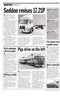
Overhauling a multi-speed gearbox need not be a daunting task. ZF's 16-speed Ecosplit is a basic four-speed box sandwiched between a splitter and a range change. Workshop went along to ZF to see how to tackle the job.
This article will deal with the main gear cluster of the 16 S 130. One word of warning on the range change: If the output shaft's seal needs replacing the flange must be warmed and pushed on with a special tool. Driving it on by hitting it will push the planetary carrier into the main housing and destroy the transmission.
John Oliver, who performed the operation, has over 10 years experience with ZF and says the Ecosplit is not a difficult box to work on. But it is essential to have a workshop manual to identify each item and show its correct position by the part number stamped upon it.
The strip down
Having removed the gearbox from the vehicle and taken off all the ancillaries the strip down starts with the selectors situated below the gear lever.
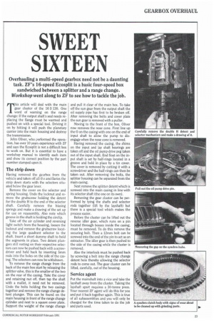
Remove the cover on the selector and spring housing. Undo the locknut and remove the grubscrew holding the detent for the double H to the end of the selector shaft. Carefully remove the biasing springs and make a drawing of the set up for use on reassembly. Also note which groove in the shaft is holding the circlip, Take off the air cylinder and reversing light switch from the housing, loosen the locknut and remove the grubscrew locating the large quadrant selector to the shaft. Insert a short dummy shaft to hold the segments in place. Two detent plungers still resting on their respective selectors can now be pushed back with a screwdriver and held back by inserting 5mm rods into the holes on the side of the casing. The selectors can now be withdrawn.
To remove the range change from the back of the main box start by releasing the splitter valve, this is the smaller of the two on the rear of the casing. Take the cover and retaining nut off, then tap the shaft with a mallet, it need not be removed. Undo the bolts holding the two casings together and remove the range change detent plunger. This can be found on the main housing in front of the range change cylinder and next to a square cover plate. Support the weight of the range change
and pull it clear of the main box. To take off the sun gear from the output shaft the oil supply pipe has first to be broken off. After removing the bolts and cover plate the sun gear is removed with a puller.
Moving to the front of the box, Oliver now removes the nose cone. First line up the 0 on the casing with one on the end of input shaft to allow the pump to disengage when the nose cone is removed.
Having removed the casing, the shims on the input and lay shaft bearings are taken off and the oil pump drive peg taken out of the input shaft. End float on the input shaft is set by half-rings located in a groove and held in place by a tin cover. The cover is removed by cutting it with a screwdriver and the half-rings can then be taken out. After removing the bolts, the splitter housing can be separated from the main casing.
Next remove the splitter detent which is screwed into the main casing in line with its selector shaft (the one on its own).
Removing the gear cluster can be performed by tying the shafts and selector rods together (lift by the layshaft) but there is a special tool which makes the process easier.
Before the cluster can be lifted out the reverse idler gear, which runs on a pin located through bosses inside the casing, must be removed. To do this remove the securing bolt. Then a 12mm bolt can be screwed into the end of the pin to act as an extractor. The idler gear is then pushed to the side of the casing while the cluster is removed.
Also the interlock must be pushed back by screwing a bolt into the range change detent hole thereby allowing the selector rods to come out. The gear cluster can be lifted, carefully, out of the housing.
Service agent
Put the mainshaft into a vice and take the layshaft away from the cluster. Taking the layshaft apart requires a 30-tonne press. Your nearest ZF agent will do this for you and put it back together again. This is true of all subassemblies and you will only be charged for the time taken to do the job and parts used. Next the selector rods can be removed starting with reverse then first/second, third/fourth and finally the splitter. Check the fulcrum pads for wear. If the sides are marked it indicates there has been difficulty engaging gears.
You are now left with the input/ mainshaft. The splitter section can be lifted off, leaving the mainshaft with four forward and reverse gears.
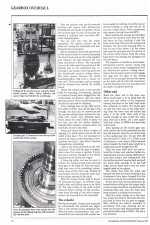
Before taking the mainshaft apart check all the synchro hubs for wear by squeezing the clutch body and synchro ring together and measure the gap between the two faces (minimum 0.8imm). The mainshaft can now be taken apart by peening out the locking tabs on the castellated nut, removing it and using a three-leg puller on the third/fourth synchro sliding sleeve. But place spacers between the clutch housinWsynchro ring first to ensure an even pull. Three plungers and six springs will be released from behind the sliding sleeve.
Check the conical part of the synchro body for scouring, discolouring, glazing or material having been dragged into the semicircular oil grooves. Also the radial grooved section of the synchronising ring should be inspected for chipping.
If any damage does not go right across the width of either face and the gap is big enough, the faces can be cleaned up and the synchronising action restored by lapping with coarse valve grinding paste. Place about five small blobs of paste on the face, put the two havles together, keeping them parallel, and give about six half turns of one in the other.
Clean and check that there is signs of lapping (in a lined pattern) across the full width of the faces. "It is not necessary to remove all traces of discolouring or scoring from the faces-, says Oliver. Recheck the gap before rebuilding.
Look at the dovetailed teeth on the sliding sleeve. These hold the gear in engagement when the torque is applied. If worn the sleeve must be changed or the rebuilt transmission will jump out of gear.
A three-leg puller can now be used to remove the synchronising body allowing third gear to be lifted off. Turn the mainshaft over now as the remaining components come off the other end. Pulling off reverse gear will also bring the inner race of the output bearing off the shaft.
Next the reverse clutch body is drawn off allowing first gear, its synchro ring, clutch body and sliding sleeve to be lifted off. The only circlip on the shaft is then removed before pulling off the synchroniser body allowing all the other components to be removed from the mainshaft.
The rebuild
Having thoroughly cleaned and inspected all components the rebuild can begin. This is the reverse of the stripdown but there are extra considerations. Any component that was removed with a puller has to be heated for refitting. To do this use an electric hotplate or drop into hot oil, do not use a naked flame. Most components only require heating to around 90°C.
When putting the springs and plungers back into the synchro hubs drop the sliding sleeve on first, pushing it past the holes in the hub. Then put the springs and plungers into the holes allowing them to rest on top of the sleeve. Lift the sleeve and push the plungers into the groove in the centre of the sleeve. Push the sleeve back down; the springs and plungers will slot into place.
The sequence of rebuild is: second gear, first/second synchro carrier, circlip (tap round to ensure proper engagement) then the first/second synchro sliding sleeve. Next is the first gear synchro ring (engage the dogs into the gaps in the sliding sleeve). Fit reverse gear and put the spacer on the shaft with the flat side innermost, heat the bearing inner race and drop onto the shaft to complete that end.
Other end
Build the other end in the same way. When fourth gear is to be fitted heat the inner race and rollers of the innermost bearing and drop on the shaft (lube holes face outwards on both). Put fourth gear on with the outer race of the outer bearing. Heat the inner race and rollers and place it in the shaft. Wait until it has cooled enough to pass inside the outer race, then tap it home. Use a new castellated nut, torque to 500Nm and peen tabs over to lock.
After putting on the fourth gear synchro clutch body fit the mainshaft into the box and measure from the top of the body to the casting (see pic). On our 16S 130 this should be 27.7mm ±0.1. If this is out of tolerance a new spacer (fitted immediately beneath the fourth gear synchro) is needed and can be bought from 2F.
Take the main shaft back out and rebuild the cluster and selectors before installing back into the casing. Refit the reverse idler using a new locking bolt. Put the splitter/selector housing back and pull the input shaft upwards to fit the half rings. Secure them with a new tin cover tapped under in four places.
The shims that limit the input and layshaft end float will need checking if any components have been changed. For this it is best to consult the workshop manual.
At the other end, the sun gear has to be heated before refitting to the output shaft. A new oil pipe should be inserted into the retaining plate and, once the bolts have been inserted, a locking wire is put on.
Offer the range change up to the main box, locate the selector then turn the output shaft to allow the sun gear to engage. After refitting the selector assembly in accordance with your drawing, the detents can be put back using sealing compound and tightening to 50Nm. The job is now finished.