


Axle Shaft is Suspension Link
Page 88
If you've noticed an error in this article please click here to report it so we can fix it.
AN independent suspension system in which the support links are used for additional duties is shown in patent No. 788,577, Althvugh intended principally for steered non-driving wheels, it can also be adapted to those transmitting the drive. (Daimler-Benz A.G., StuttgartUnterturkheim, Germany.) The drawing shows a non-driven wheel mounted according to the scheme. The upper link (I) is a single shaft and is mounted in line with the wheel axis Besides being a suspension member, it is universally jointed and transmits either driving or braking torque. The lower link (2) is a fabricated structure and is made as stiff as possible because it has to resist the bulk of the road shocks. The kind-pin -is held in this part and its axis aligns with the centre of the universal joint (3). The brake drum and mechanism are located inboard (as shown at 4) so that their weight is not added to the unsprung mass. Either torsion bars or coil springs may be used for the resilient members.
A VALVE-SEAT GRINDER PATENT No. 788,888 shows a valve • seat grinding machine using an emery wheel revolving at 15,000 r.p.m. The wheel is also given an orbital motion about the valve axis so that it is cutting on one spot only at ally givenmoment. (I Dreyer, 93 Kaufmann Dufourstrasse, atrich, Switzerland.) SELF-SEALING PISTON nESCRIBED as being suitable for pumps, blowers and internal-combustion engines, a design for an improved piston forms the subject of patent No. 788,253. (Diesel Engine Company of Texas, Houston, Texas, U.S.A.) As shown, a piston body (I) is made conical on its outer diameter and has fitted to it a multi-layer ring (2). This is actually one length of material, close coiled to eliminate all but one gap. the coiling is not uniformally but consists of plane rings which are interconnected. The principle of the scheme is that piston movement applies al, outward force to the composite ring and so maintains a good fit on the cylinder walls.
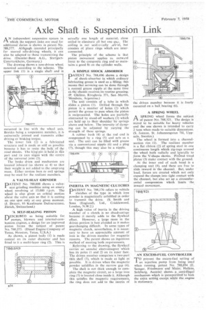
A SIMPLE SHOCK ABSORBER
PATENT No. 788,496 shows a designof shock-absorber in which ordinary lubricating grease is used as a filling; this means. that servicing can be done through a normal grease nipple at the same time as.the-chassis receives its routine greasing. (P. Ghilino, Rivadavia 371, San. Martin,. Mendoza, Argentina.) The unit consists of a tube in which slides a piston (1). Drilled through the piston is .a number of holes (2) which permit the grease to pass when the piston is reciprocated. The holes are partially obstructed by stand-off washers (3) which are held up to their shoulder by springs above and below. The intensity of damping can be adjusted by varying the strength of these springs. A rubber bush (4) at the rod end is compressed by a ring (5) and acts as a seal. The unit can be filled with grease via a conventional nipple (6) and a plug (7), though this may also be a nipple.
INERTIA IN MAGNETIC CLUTCHES DATENT No. 788,176 refers to vehicle clutches of the type in which iron powder is magnetically solidified in order to transmit the drive. (S. Smith and Sons (England), Ltd., Cricklewood, London, N.W.2.) A high value of inertia in the driving member of a clutch, is no disadvantage because it merely adds to the flywheel effect. However, a large mass in the driven portion is best avoided as it makes gearchanging difficult. In some types of magnetic clutch, nevertheless, it is necessary to have an appreciable amount of iron in the driven member for magnetic reasons. The patent shows an ingenious method of meeting both requirements. Referring to the drawing, -the flywheel carries an annular electromagnet which hasits poles (I and 2) on its inner face. The driven member comprises-a two-part thin shell (3), which is made as light as possible. It is driven when the magnetic powder solidifies in the narrow gap (4). The shell is not thick enough to complete the magnetic circuit, so a large iron ring (5) is located close inside it. Although this satisfies the magnetic requirements, the ring does not add. to the inertia of
A SPRING WHEEL
ASPRING wheel forms the subject of patent No. 788,321. The design is stated to be suitable for heavy vehicles and the one shown is intended to carry 2 tons when made to suitable dimensions. (S. Jonzon, St. Johannesgatan 711, Uppsala, Sweden.) • The wheel is formed into a channelsection rim (1). The resilient member is a flat ribbon (2) of spring steel in one continuous length which zig-zags around the wheel both radially arid laterally to form the V-shape shown. PivOted tread plates (3) make contact with the ground. At the inner end of each bend is a clamping unit (4), and these are free to slide inward in the channel. But, under load, forces are created which not only expand the clamps into tight contact with the channel, but also set up a circumferential compression which limits • the inward movement.
AN EXCESS-FUEL CONTROLLER
T°prevent the excess-fuel setting of an injection pump front being used when running. patent No. 788,894 (E. Satzger, Friedmann and Maier, Hallein, Salzburg, Austria) shows a centrifugal mechanism which is incorporated to lock the extra setting except while the engine is stationary.