


An Injection Pump of Simple Design T HE conventional type of
Page 28
If you've noticed an error in this article please click here to report it so we can fix it.
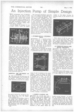
injection pump has to be made to close tolerances, and on this account it is an 'expensive item. Patent No. 615,478 shows a pump which is claimed to be more simple to manufacture because of. the larger permissible tolerances. The patentee is T. Duncan, Sydney, New South Wales, Australia.
In this design, the plungers (1) are arranged radially round the central
spindle (2). They are operated by a roller (3) which travels round with the spindle and makes contact with each plunger in turn, forcing it outwards for its delivery stroke. The plungers return to their innermost position under spring forde. "Pipes 4 form the delivery lines, and all the, inlets branch from a common pipe (5). The inner system of piping (6) is for a supply-of oil to all working' parts; this is necessary if the fuel pumped be itself non-lubricating.
• Adjustment for output is Made in the following manner; the roller (3) is journalled in a spring-loaded crossslide, and can be moved to a larger or smaller effective radius by the --moveAnent of a wedge-shaped slider (7) 'housed in the centre of the main Spindle. • The external control lever is 'attached to the sliding wedge by a freely journalled collar (8).
ASSISTING THE RE-TIMING OF ENGINES
rtA JOB which is by no means easy on a modern engine is the re-tithing of the ignition. To render this an automatic operation is the aim of a scheme
described in patent No. 614,366, by the Ford Motor Co., Ltd., 88, Regent Street, London, W.I.
It is achieved by providing a hole in the timing case through which a locating pin can be inserted. The engine is then rotated until the pin drops into another hole in the timing gearwheel. This effectually locks the engine in a specific position.
A34 The interruptor-distributor unit then has to be similarly located, and this is done in the following manner: Over the studs which normally carry the timer is placed a special washer, shown at 1 in the drawing. The driving sleeve is then loosened on its spindle, and rotated until a slot in it lines up with a slot (2) in the washer. The slot is offset in both units to prevent it being half-aturn out.. The locking screw is finally tightened, the washer removed, and the timer placed in position with assurance that it is correctly set. The timer must, of course, be pre-set during manufacture, and the patent envisages that this has been done.
A RUBBER-METAL UNIVERSAL JOINT
INTENDED for a gearbox-to-backaxle coupling, a universal joint, shown in patent No. 615,540, comesfrom Metalastik, Ltd., and A. Hirst, both of Evington Valley 'Road, Leicester. By reason of its construction, the joint renders the provision of a centring bush unnecessary.
Referring to the drawing, the driving member carries a metal cone (1) which is sandwiched between a pair of metal cones (2 anti 3) attached to the output member. Layers of rubber are interposed between the cones, and the whole is bonded into a unit. A ring of clamping bolts (4) is provided for the purpose of pre-stressing the rubber, the exact degree being determined by the thickness of a packing washer' (5). Pre-stressing'in a rotary sense can also be obtained; this is done by bonding the parts with the bolt-holes slightly out of register.' When the bolts are inserted, they pull the holes into line and so impart a measure of torsional loading. To maintain the drive should the rubber fail, an emergency metalto-metal coupling is incorporated.
A SIMPLE LOADING AID
PATENT No. 617,198 deals with a simple loading device adaptable to practically ant type of body. The patentee is R. Warlord, Celia Villa, New Road, Broomfield, near Chelmsford. Reference to the drawing will slaqw a roller (1) backed up by smaller rollers (2 and 3). The latter are mounted in web pieces which are
welded to the plates forming tin securing means to the tail-end of th( barb/ These plates, as will be seen, also serve to retain the large roller. With such a device fitted, better control of the packages being loaded is Maintamed, whilst the effort on the part of the loaders is considerably reduced.
AN IMPROVED MEANS FOR BRAKE ADJUSTING
PATENT No. 614,692 refers to brakes in which the " off " position of the shoes is automatically maintained at a constant distance from the drum. The patentees, J. Pratt and 6. Manley, both of Guildhall Buildings, Navigation Street,, Birmingham, disclose an improved scheme particularly applicable to the well-known Girling brake. , The drawing shows sufficient of the brake mechanism to illustrate the invention. The shoe .shown carries a "
feeler"' (I), positioned between the drum and a stop-pin (2), and frictionally attached to the shoe, so that as the shoe moves towards the " off " position, it is arrested by the stop pin at the point giving the minimum practicable clearance.
The chief point of. the patent is the means . for applying the braking force to a shoe which, as it wears, is con
tinuaTly moving outwards. To achieve this, the expander pushes the shoe via a rockable arm (3) which can slide on a pin (4) attached to the shoe. When unloaded, the shoes can move easily with respect to the arm, but when force is applied by the expander, the arm tilts, jams on the pin and all parts move as one.