


Injection Pump Without a No-load Governor
Page 34
If you've noticed an error in this article please click here to report it so we can fix it.
• rlA CCORDING to patent No. 549981, the conventional injection pump
• suffers from a defect in that its delivery at low speeds is less than it should be, due to leakage. This is serious during idling, because it means that if the engine speed falls slightly, the fuel supply is further diminished and the engine stops. Likewise, if the engine accelerates a little, slightly more fuel is injected; with a similar cumulative result Hence the need for an idling • • governor.
Object of the scheme • detailed at some length in the'patent is to remove the need for this. The patentee is S. A. Adolphe Saurer, Arbon, Switzerland.
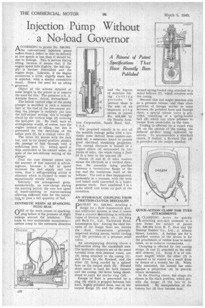
The helical control edge of the pump plunger is modified in such a manner that at the end of the low-output setting the, plunger is suddenly put into the full-output setting; this is brought about by the vertical edge (3) covering the spill-pbrt (4). By itself, such an arrangemeat would, of course, race the engine instead of idling, but this is prevented by the throttling of the inflow port (5) by a conical valve (2). The valve (2) moves with the rack bar, and in its closed-position permits the passage of fuel through only a restricting bore (1). Idling speed is thus controlled to its correct value, in spite of the full-delivery setting of the plunger.
That the time element enters into the amount of fuel injected is advantageous, because a fall in speed increases the fuel supply and .vice versa, thus a self-governing action is obtained which is claimed to result in exceptionally steady idling.
Similarly; the arrangement gives, automatically, an over-charge during the starting period, the very low speed of, hand-cranking or starter-turning allowing sufficient time foe the restrictipn to pass a full quantity of /uel.
SYNTHETIC RESIN AS SPARKINGPLUG SEAL .ONE of the main causes of sparking. plug failure is the presence of slight leakage around the insulator. • This leads to two undesirable occurrences— carbon creep in the outwards direction
and the ingress ' of moisture during eooling 'periods. -To prevent these is the aim. of an improved plug shown in patent No. 549,580 by the Bendix Aviation Corporation, South Bend, Ind., U.S.A.
The proposed remedy is to seal all the possible leakage paths with a synthetic resin derived from cashew-nutshell oil. a substance found to possess good electrical insulating properties: The central electrode is housed in a copper sleeve (4). surrounded by two layers of mica, the whole being a piish fit in a bore in the dap-nut (3).
Stacks (2 and 5) of mica washers secure the electrode in a vertical direction, the assembly being pinched between a turned-over flange at the top and the mushroom head at the bottom. The unit is then impregnated, preferably in a vacuum, with the resin and baked until converted to 'a homogeneous whole. Part numbered 1 is a radio shield and forms no part of the invention.
AN HYDRAULIC COUPLING FROM
FRICTION-CLUTCH S1ECIAL1ST DATENT No. 549,951, detailing a design for a fluid transmission gear,. has additional interest in that it comes from a concern.lpecializing in orthodox types of friction clutch, viz., the Borg and Beck Co., Ltd., Tachbrook Road, Leamington Spa. Among the chief features of the design there are, besides the fluid transmission principle, improved sealing means, better cooling and the provision of a pressure relief valve.
An accompanying drawing shows a half-section along the crankshaft axis. The hydraulic elements are of the.usual toroidal. form with internal vanes, one (9) being attached to the casing (1), and driven by. the flywheel, and the other (2) being carried by a splined boss on the output shaft (5). Pressed sheet metal is used for both runners and the casing, the latter being shouldered to carry the starter ring (10).
Escape of fluid is prevented by a ring (6) which is gripped between two hard, highly polished faces, one on the output flange (5) and the other on a
second spring-loaded ring attached to "a metal bellows (7), which revolves with the casing.
Because this seal might function also as a pressure release, and thus allow particles of foreign matter to enter between the polished faces and damage them, a special release valve is provided, consisting of a spring-loaded ball (8) which can allow pressure to escape from cross-holes in the boss.
Cooling is effected by a. vaned ring (3) on the outside of the casing, the induced air-flow being indicated by arrows. To accommodate a standard clutch, if desired, a flywheel disc (4) is provided on the output member.
QUICK-ACTION CLAMP FOR TYRE ATTACHMENTS
ACLAMPING device for quickly attaching non-skid elements to a tyre forms the subject of patent No. 549,894 from R. F. Daw and the Dunlop Rubber Co., Ltd., .1, Albany Street, London. A further use for a modified version of the device is for the attachment of rubber hose to metal tubes, as in'radiator connections.
Clamping is effected by two canvas straps (5 and 2) attached to the nonskid element, (1). Strap 5 is of constant length': whilst the other (2) is adapted to he wound on a small drum by means of a tommy bar (3). When fully tensioned, the tommy bar rests against a projection (4) to prevent return movement.
In the drawing above, the straps are shown in the slack position, which permits the longer of the two to be unhooked. By manipulation of the tommy bar (3) they become taut.