


17 Ratios and Changes Without Break of Drive
Page 20
Page 21
If you've noticed an error in this article please click here to report it so we can fix it.
LARGELY for the sake of its high efficiency the type , of gearbox einploying meshing toothed wheels has retained its position of popularity in the face of competition from numerous alternative types with better characteristics , in other directions. Lack of infinite variability of ratio between limits and inability to change tha ratio -without momentarily ceasing to transmit torque are the faults of the conventional gearbox which, -more often than not, are outweighed by the high degree of satisfaction it affords in most other respects.
Worthy of Its Ingenious Predecessor
Now a design has appeared in which the former of those faults is minimiZed and the latter virtually eliminated. It _ is the invention of Mr. }1 F.. Hobbs, 25, Woodcote Road, Leamington Spa, who, as readers may remember, was responsible for the infinitely variable gear that caused 23o. much interest at Olympia in 1935, where it was exhibited on the Maudslay ,stand:' A description and explanation appeared in this paper on November 15 of that year, whilst in the following December, on the 20th, we published an article by Mr. Hobbs entitled " The Claims of the Contr011able Infinitely Variable Gear."
This new Hobbs transmission unit provides 17 ratios which may be so close as to fulfil in practice the requirements met theoretically by the infinitely variable type, and these can be brought into use while full torque is being transmitted, only a negligibly small drop in output occurring for the instant in which the change is made.
According to a recently published patent specification, No. 549,988, which describes the device in 23 pages illustrated by 22 drawings, the prin. ciple is applicable to the heaviest chassis, a unit for a 400 h.p. armoured vehicle being detailed.
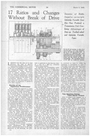
In principle' the transmission works thus: the input drive is divided, by a system of clutches and a differential gear, into two parts which can be variously proportioned from zero to maximum, and these are directed, respectively, to two of a .number of different ratios in a step-up gearbox.. At first, one ratio handles the entire drive; then the drive is shargd in three proportions, one after the other, and next the other gearbox ratio receives and passes on the full torque, the process being subsequently repeated with other gearbox ratio.
The mechanism comprises two units described by the inventor as the distributor (on the left in the accompanying drawing) and the gearbox (on the right). The input 'shaft (9) ig fixed to the, distributor casing and thence torque is transmitted in sequence, as changes are made, by five clutches to two concentric intermediate shafts (0•
and 7). These, singly or together, pass on the torque via a layshaft (19) to the output shaft (14).
The total of 17 close forward ,ratios is afforded in the following manner s-To obtain first gear, clutch 5 alone ia. engaged and all torque goes direct to shaft 61 to which the clutch plate is keyed. Thus, wheel 10 is driven. Wheel 18 is clutched to the layshaft and wheel 13 to the output shaft. Wheel 16 is also clutched to the layshaft, but wheel_ 12 and shaft 7, to whic,h It is keyed, are free; this fact is significant as will be revealed later.
For second gear no change is made in the gearbox, but, in the distributor, clutch 5 is freed and 4 engaged. Nov,' the drive goes to a differential assembly (8) and the major part of the torque
is conveyed to shaft 6, whilst the remainder is transmitted to shaft 7. This shaft, as has just been mentioned, is rotating with wheel 12. Therefore, bevel 20 of the differential (8) is turning. Accordingly, the double-planet assembly, meshing on the left with 20 and on the right with the bevel on clutch-.disc 4, Will' revolve around shaft 7 (as it would also, of course, if 20 were merely held). This means that bevel 21, fixed-to shaft 0, is turning its shaft at a speed higher than under the conditions of first gear.
It must be appreciated, furthermore, that , whilst the bigger part of the torque is being conveyed by the same gearbox wheels as before, namely 10, 18; 15 and 13, the remainder is transmitted by shaft 7, and wheels 12 and 16, whereafter the route is common.
Two Gearbox Ratios Take Equal Torque Now, if clutch 3 be engaged and 4 released, the differential housing receives the drive and the torque is shared equally between shafts 6 and 7, with another increase in the speed of the output-shaft (14) in relation to that of the input-shaft (9).
With clutches 2 and 1, respectively, the greater part and the whole of the torque go to shaft 7, in the same manner as they went to shaft 6 when clutches 4 and 5 were in operation.
It is of note that when all the drive. is being conveyed by shaft 7, shaft 6 is under no load. This opportunity, therefore, is taken to make the necessary change in the gearbox for the next ratio. This comprises clutching 11 to the outer intermediate shaft (6) and declutching simultaneously wheel 18 from the layshaft (19). Because of the ability always to do this, prior to bringing the two shafts into combined use. gearbox as well as distributor changes can be effected without any break in the drive. Therein lies the significance mentioned earlier in connection with the clutch of wheel 16:
There is ground -for arguing that the release of one distributor clutch and the 'engagement of another, when both arc under load, constitutes an interruptionto the drive, but the ratios are so close. that the power loss represented is only about 5 per cent, of that developed and may, therefore, be regarded as
It will be noted that dog clutches. are employed throughout in the gearbox, and that each is provided with a synchronizing device. As depicted in this illustration they are hydraulically operated as are the friction clutches in the distributor, which, incidentally, transmit only engine torque. .
Some readers may be momentarily puzzled to comprehend why 17 and not 20 ratios are afforded by the combination of five different torque distributions with apparently four gearbox speeds. The explanation is simple. One torque distribution is common to each sequence; for example, after the successive use of clutches 1, 2, 3, 4 and 5, 4 is brought Into service again, then 3, 2 and 1, and next 2 for the third time, and so on. After the first five, there is only four to be added each of the three times.
The foregoing relates to only one embodiment of the invention. There are others, including one functioning on the epiEyclic principle, also various modifications of the controlling means.