


A New Carburetter of Marked Simplicity
Page 63
If you've noticed an error in this article please click here to report it so we can fix it.
TN the earliest days of the internal-combustion engine the surface carburetter was almost universal. Its general principle was the passage of air over a comparatively large area of fuel in such a manner that the air picked up a proportion of the volatile liquid and the two formed the explosive mixture. • In certain later designs, such as the Lanehester, saturated wicks were exposed to the air.
A feature of the new Apex carburetter just introduced by Inventions Developments, Ltd., Sardinia . House, Kingsway, London, W.C.2, is the use of a fuel-soakedfabric jacket around a metal body, the whole being termed a " bulb." This component is situated in the choke tube. To a certain extent it combines the features of the jet and surface-evaporation types. It does the work normally allotted to the main jet.
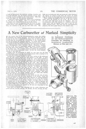
Dealing with the instrument in detail, we may pass over the float chamber briefly, as it is of the conventional .pattern with a seating in its base and bob-weights controlling the needle.
Screwed into a passage formed in the lower casting is the submerged main .jet ; this merely. meters the fuel Passing to the bulb. A gauze filtering-sleeve surrounds the base of the jet. After being metered by this Orifice,the fuel travels through passages in the Resting, then up the bore of the bulb and out through eight radial holes to the fabric sleeve which. surrotinds the meta' portion of the bulb. Here the petrol is exposed to the air Passing' through the choke tube and forms the mixture.
In one side of the upper casting is the pilot-jet chamber ;a regulating screw is provided fc(r the air inlet to this jet. To balance the pressure in the carburetter outlet and that in the choke tube, thus avoiding suction on the pilofjet when the throttle is opened, a passage is.made between the pilot chamber and the choke tube. Both jets, the bulb and the float chamber form part ofthe lower assembly : The upper portion consists of the mixing chamber with the choke and throttle. ,Both this and the lower portion. are die-castings.
Among the advantages claimed for the design are the ease of maintenance consequent upon the great simplicity of the layout. From test results put before us (these having been obtained in various factories) the acceleration and economy given by the Apex are above the average. This is particularly so at partial throttle openings—that is, during the greater part of the running time. One set of figures showing this is taken from a test with a 110-mm. bore engine. When the engine was developing 26.66 bh.p. at 1,000 r.p.m. the Apex gave a consumption of .07 pint per b.h.p.-hour, as opposed to .77. 'pint per b.h.p.-hour in the case of another carburetter.
Four sizes are listed. The following are the outlet diameters and prices: 26 mm., £5 10s. ; 30 mm., £6; 85 mm., £6 15s.; 42 Run., 15s.