


AN ENTIRELY NEW
Page 58
Page 59
Page 60
Page 61
If you've noticed an error in this article please click here to report it so we can fix it.
DUSTLESS
REFUSE COLLECTOR
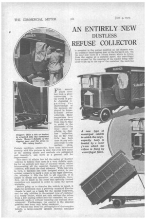
FOR several years there has been a great controversy in the world of public cleansing regarding the shortcomings of the methods employed in houseto-house refuse collection. Many suggestions have been put forward from time to time to assist in the attainment of the ideal state of affairs, i.e., dust
less collection, but so far very little has been done on any suitable scale to hell) matters along. Certain machines, admittedly, have been introduced recently with this purpose in view, but even now many of the existing means and methods are antiquated and insanitary, and there is a general call for improvement.
This state of affairs has led the maker of Karrier vehicles to believe that there is a very definite opening for an entirely new type of machine which, whilst incorporating all the essential features of a refuse collector, will tivoid the dust nuisance. With this idea in view, a machine has been designed which, in our opinion, appears to mark a step in the right direction, for, although it fills the bill in all respects, it is simple in design and operation ; no complaints, therefore, can be made in the sense that specially trained operatives are required in order to make the system workable.
Before going on to describe the vehicle in detail, it might be mentioned that a perfectly standard Karrier chassis is used as a basis for the special bodywork, and the only addition to the normal type of container is a rotary loader, which not only conveys the refuse from a low loading orifice into the container, but auto matically packs it without-requiring any manual effort whatever. Furthermore, the control is the simplest powible—one lever only being employed.
As will be seen from the photographs of the complete :vehicle, a large-capacity entirely enclosed container B32
(Upper) How a bin or basket is emptied into the curtained chute. (Lower) Details of the tipping gear and the drive to the rotary loader.
is mounted in the normal position on the chassis with an ordinary hand-tipping gear at the forward end. On the near side there is a rotary loader which is driven from the engine at a suitable speed, the centrifugal force caused by the rotation of the loader being sufficient to lift up to the top of the container the material
thrown into the chute and to throw it with force• towards the back of the body. This, of course, ensures that the loading will progress from the rear to the front, so that the container can always be completely filled without it tieing necessary to shovel the refuse away from the mouth of the loader.
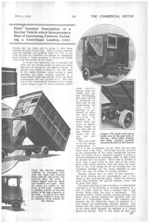
It would seem opportune now to describe the rotor and the driving media, as there are many features of interest in the general layout. A special hack plate Is fitted to the rear face of the engine flywheel which carries a chain sprocket, the chain running upwards to a countershaft lying immediately above the main transmission line and parallel to it. The rear end of this countershaft terminates in a easing which houses a pair of worm reduction gears; cross shafts emerge from the easing and run into self-aligning ball races carried in standards on each side Of the worm casing. On one side a sprocket is arranged to drive the rotor shaft through the medium • of a short chain, the rotor, of course, being housed on the near .side of the vehicle, between the cab and the Container.
The rotor itself is of very simple construction. It is 3 ft. 6 ins, in diameter, 22 ins, wide and has nine vanes each 6 ins. deep. Particular interest attaches to the construction of the vanes themselves, because they are made up in a composite manner in order to prevent jamming if an unusually bulky or stiff article he thrown into the loader. Each vane is framed in steel, with a cane brush on each side of the centre piece; this centre, however, does not touch the inner face of the rotor casing as do the brushes, but the necessary strength for the whole assembly to cope with any type of refuse is thereby attained.
Mention should here be made of two features--the. drive take-up on the countershaft, and a free wheel on the rotor-driving shaft. These two features have been included for special reasons, which will be dealt with later.
The chain sprocket on the secondary or countershaft (marked A in the drawing) is actually mounted on a pair, of roller races in such a manner that it can
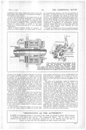
revolve freely when the rotor is stationary. The. sprocket itself is (when driving) pinched between two fabric discs, thereby 'making the assembly take the form of a single-plate clutch. The requisite endpressure for the clutch-like device is supplied in a very simple but nevertheless effective manner. One friction disc (the outer) is attached to a sleeve mounted on the main shaft through the medium of a coarse square-cut thread: Now it will easily be seen that if the sleeve and the fabric be pressed into contact with the chain sprocket, by .a suitable operating gear, the driving action of the sprocket will tend to tighten the two components together because the thread inside the sleeve will naturally cause an increasing end thrust to be applied, due to the rotation of the driven member and the frictional contact between the two elements.
This action enables the drive to be taken up smoothly and progressively according to the speed of the driven member and the loads involved. To disengage the drive, a band brake is contracted on to the sleeve, which causes the thread to reverse the end-wise pressure, with the result that the friction surfaces are forced apart, thereby bringing the whole assembly quickly to a standstill. The idea behind this arrangement is, of course, to enable the vehicle to be driven ordinarily on the road, and when changing gear to prevent the inertia of the countershaft and the rotor from being added to that of the engine flywheel. The rotor, as might be expected, is a very weighty affair and if it were allowed always to revolve with the power unit would make the task of the driver extremely difficult.
For similar reasons, a free wheel or "one-direction-drive" is incorporated in the rotor spindle. In ether words, the rotor can over run its driving shaft, so that • when the drive from the engine is disengaged (by applying the brake band) the inertia of the rotor is atttematicallY cut out.
In passing, the design of the rotorshaft free wheel seems worthy of comment, again on account of its simplicity. The chain sprocket is attached to a sleeve which, to all intents and purposes, is a spiral rectangularly sectioned spring. An interference of .004 in. is arranged between the inner face of the sleeve and the journal portion of the shaft When the sleeve is rotated in the driving direction the tail-end of the " spring " drags on the shaft (by virtue of the interference in diameters of the two elements) and so a tightening action is started which gradually continues throughout the length of the spring. In a few revolutions the driving and driven components become locked to one another, but the moment the driving effort is withdrawn the " spring " opens out and allows the n34 rotor shaft to overrun the sprocket which drives it We can now consider hoW the device works in actual practice. In the first place it might be stated; that the loading height (from the pavement) is but 3 ft. 6 ins., or about 4 ft. if measured when the vehicle is .standing in the middle of the roadway. The aperture is provided . with a collapsible hood and side screen in order thoroughly to encase the open end of the ashbin or other container normally used for refuse.
The rubbish is " shot" into the rotary loader down the chute, whence it is conveyed directly into the inner area of the rotor. It is then partially screened and separated by the partitions formed by the vanes, and by centrifugal force is thrown violently towards the rear of the container. The force is sufficient to pack the refuse firmly at the back of the body and gradually to fill it up towards the delivery end. All manner of refuse can be dealt with, and the delivery action on ashes, paper, books, bottles, tins, etc., is the same, although the size of bulky articles, such as boxes, is controlled by the size of the separating partitions (in this particular case the maximum size is about 10 ins_ by 18 ins.).
Refuse that cannot -pass will not impede the passage of the rest of the rubbish, whilst any excess of bulky articles which may accumulate can readily be
withdrawn (after tieing riddled and cleaned from the other refuse) and deposited in the container through a door fitted for that purpose.
A very interesting point in the construction of the vehicle is that the driving mechanism is so arranged that the rotary loader can remain in operation even when the vehicle is moving slewly.. Travelling loading can, therefore, be employed where conditions permit, without the driver having to attend to the • dual operations of driving and loading—a very important consideration.
There is another feature worthy of comment. It desired two rotary, loaders can quite easily be incor.
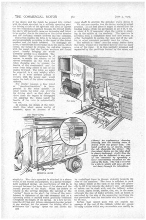
porated in the design of. vehicles intended for use in very thickly populated districts. Loading could then be carried out by operatives on both sides of the street with an absolute minimum loss of time. In the case of the machine under review, however, only one loader is employed; the refuse can be distributed over the whole width of the body,, however, by means of a metal, deflector which controls the angle at which the rubbish is thrown into the van. This angle of throw is controlled by the men who are performing the task of loading, by a simple lever fitted to the outside of the body. A drawing accompanying this article illustrates this point quite clearly.
Before concluding it would seem to be opportune to give a brief outline of the layout for the chassis. The illustrations clearly indicate that a specially low frame level has been attained by employing small wheels.and solid tyres, in addition to fairly fiat springs and a: generally compacted design for the main chassis components. With wheelbase and traek dintensions of 12 ft. and 4 ft. 9 ins, respectively, a large body space is provided without excessive overhang, whilst (by virtue of the compactness) manceuvring in confined spaces is relatively easy.
A four-cylindered side-valve engine of 95 mm. bore and 140 mm. piston stroke provides the power both for transportation purposes and for the operation of the rotor. At 1,000 r.p.m. 26 b.h.p. is developed, whilst at maximum revolutions the output is no less than 40 b.h.p. An adjustable cone-type clutch and a fourforward-speed gearbox with right-hand controls transmit the drive through an open propeller shaft to an overhead worm to the rear axle which, like the front counterpart, is suspended on semi-elliptic springs; auxiliary springs fitted above the rear axle come into operation with overload, thus relieving the main springs of undue stress.
As might be expected, the driver is seated alongside the engine, in.it as this unit is placed low in the chassis and is totally enclosed by a cover, accommodation can bee provided for a passenger in the centre of the cab ; there is another auxiliary seat on the near side so that in all tivo men can be carried in addition to the driver.
The body of the particular vehicle hi question has a capacity of approximately 15 cubic yds.; it is 12 ft. long, 6 ft. 6 ins. wide and 4 ft. 9 ins. high, with a 4-in taper in width to .facilitate tipping. This container, however, is not claimed to be an ideal size, but it has been built in order to show the potentialities of the rotary loader. Great care has been taken to make the container dust-tight. To this end the tipping doors are very carefully fitted to the body frame and the roof is covered by a specially fine fabric, which allows the egress of air but retains even very fine particles of dust—much after the fashion of a vacuumcleaner container, or dust-bag. This latter feature is essential to the design, because the rotor pumps air into the container, thereby creating a pressure inside, which must be relieved to obtain efficient working.
Altogether, this new Karrier product is a very ingenious and interesting machine, well calculated to meet modern hygienic demands. We have actually witnessed the vehicle in operation in its proper sphere and we can vouch for its effectiveness.