


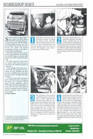
II Snell likes to start the service by draining the engine oil, leaving
Page 99
Page 100
Page 101

Page 102
If you've noticed an error in this article please click here to report it so we can fix it.
the internal checks until later.
The oil should be drained at every service. First the sound-deadening cover over the vee-eight's sump pan has to be removed. The magnetic sump plug is removed using a 19mm hex key.
The power steering reservoir is reached by lifting the front grille. Scania's schedule does not call for the fluid to be changed; the filters renewed on the MI2 service. The filter is beneath the large cap and has a bayonet lock. With the engine stopped the fluid level should be to the top mark on the dipstick; when topping use fluid to Dexron II specification.
The translucent clutch reservoir is behind the grille at the top offside. It carries maximum and minimum level marks. "If it is a long way down start looking for leaks,' says Snell. Like the power steering, the clutch fluid does not need to be changed. Top up when required with DOT 4 fluid. Also behind the grille but on the nearside is an air filter for the.cab heating/ventilation system. It is changed on the M12 service but Snell gives it a quick check to ensure it is not clogged.
3
At this point the cab is tilted and Snell turns his attention to the oil spinner. Scania engines only fil ter the oil for the turbocharger; the rest passes through a centrifuge which captures contaminants. On the vee-eight engine the spinner is at the front nearside: it should be cleaned at each service. To do this Snell removes the cover and lifts out the rotor assembly. The knurled nut is lightly clamped in a vice and loosened. With the nut removed the rotor comes away from the bottom plate to reveal the coagulated muck on the inside of the rotor cover. All the parts of the spinner must be thoroughly cleaned before reassembly. The coarse filter is dropped over the central column of the baseplate. Fit a new 0-ring on the baseplate-lip, replace the cover, making sure that the brass jets are not blocked. Replace the knurled nut and put the rotor back into the housing to check that it rotates freely, and the bearings are not worn. Before refitting the cover (with a new 0-ring) Snell cleans the sump plug, fits a new sealing washer and refills the engine through the rotor housing with 25 litres of 15W/40. On top of the engine between the cylinders are three renewable canister-type filters on a single housing. The front two are fuel filters, with the turbo oil filter behind them. Before moving the filters put some paper or rags in the vee to catch spilt oil and diesel. The turbo filter is changed at each service; the replacement must be primed with oil to prevent the turbo running without protection immediately after start up. When refitting the filter smear a little oil on the sealing ring. The two fuel filters are changed on the M6 and M12 services. There is a pre-filter on the fuel line at the front offside of the engine. It is the usual glass bowl type and should be cleaned during every service. Put the spring end into the bowl first and make sure the spigot on the element fits into the recess in the housing. A new sealing ring should be used. To bleed the fuel system on an EDC-equipped vehicle the ignition must be switched on for the fuel valve to be opened. The bleed screw is on top of the housing and the lift pump is on the front offside of the injection pump. If the engine will not start after bleeding the system loosen the spill return banjo bolt on the rear offside of the injection pump. Give a few more strokes on the lift pump and try again. While on top of the engine check the tension and condition of the fan belt. There should be 612mm of play on the belt run between the alternator and fan drive pullies. Have a general look round for oil or water leaks and sound all the major components with a small hammer. The batteries are not sealed-for-life units; the electrolyte level must be above the plastic markers.
10 Next Snell changes the
coolant filter. This is hidden behind the front offside
bumper and contains corrosion inhibitor but not antifreeze. It should be changed on the M6 and M12 services. There is a switch on the housing to stop the water draining out when the filter is removed: turn the switch to the horizontal position and remove the canister-type filter with a strap wrench. Grease the new filter's seal and do it up hand tight. Don't forget to turn the water on again. Antifreeze should be at a level to give protection down to —18°C.
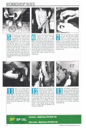
11 There is no clutch adjustment but the amount of
wear is checked by taking a measurement from the face of the servo to the back of the locknut. When the plate is new this gap is set to 6365mm. When it falls below 47mm a new clutch plate is required. "If the clutch starts to slip check this dimension first", Snell advises. Moving down into the pit Snell drains the CR880 10speed gearbox. The oil is changed on the M6 and M12 services with a simple level check on the M3. The drain plug is at the bottom offside of the gearbox with the level plug on the nearside. Both have magnets on them. They are removed using a 19mm hex key; thanks to their tapered design no sealing device is needed. Refill the gearbox with 11.5 litres of 85W/140.
Oil changes on the R770 rear axle are a repeat of the job on the gearbox. The drain plug is at the bottom of the differential housing and the level/filler plug is in the nearside of the pinion housing. Like the gearbox, the plugs are tapered, carry magnets and take a 19mm hex key. Its capacity is the same too, at 11.5 litres, and it also needs 85W/140. 14 The brake linings are
checked through inspection windows in the back plates.
Wear ridges are being introduced on some of the later Scania brake linings and all new shoes will be asbestos-free. The service limit is 8mm or lOmm for oversized drums. Although inspection windows are fitted at the top and bottom of the hackplates Snell has found that the shoes wear evenly so only one window per wheel need be used. On this vehicle the front axle brakes were in need of a reline but the linings on the other two axles had plenty of life left.
15 Automatic slack adjusters
must he checked by measur ing the distance between the brake chamber and the clevis pin; the acceptable gap is 69-71mm. Remeashre this distance with the brakes applied and subtract one figure from the other to calculate the stroke. It should be 25-44mm except on Type 30 chambers (the number is on the chamber), which should have a stroke of 30-51mm. Take care with manual adjusters — those at the front turn one way and the rear the other. Apply the brakes to check the adjustment is correct.
16 On the MG and M12 services
the cones on the rear sus pension air bellows must be cleaned. Tar and road dirt tends to build up on the cone and will chafe the rubber bellows if not removed. Using the air suspension's manual control the bags are fully inflated which exposes the cones. Simply clean all the collected matter off with some emery-paper. Inspect the condition of the air bag closely. On our vehicle this procedure has to be repeated on the second steer axle which is also air suspended.
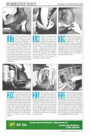
17 Snell now greases the vehicle. Starting at the front there is one grease point at
the front shackle pins and two on the spring hangers. Kingpins on both steering axles require grease at the top and bottom. All the automatic slack adjusters need greasing. Steering axles have a nipple on the wheel end of the Scam shaft, the rear axle brakes have a second nipple at the adjuster end. Propshaft Lis and slider require grease and don't forget the nipple half way up the bell housing which lubricates the clutch release bearing. There are also nipples on the second steer drag linkage.
18 During his inspection Snell
noticed that the front springs had become mis aligned with one leaf not laying directly over the top of the other. This is not uncommon for the parabolic springs on this vehicle, says Snell, and it is easily rectified — simply loosen the U-bolts and tap the mis-aligned spring back into line. Re-tighten the U-bolts to torque of 480Nm. Now give the underside of the vehicle a general inspection and sound all major components with a small hammer to ensure they are tightly attached.
19 The last job down the pit is to check the steering joints
for signs of wear. They are sealed-for-life units and Snell feels each one in turn as a colleague rocks the steering wheel. This being a twinsteer there are two sets of joints and the linkage between the axles to check. While checking for play try the Ills for wear and check the gearbox output and the differential nose bearings for lift. Any oil leaks in these areas will he obvious.
20 Air dryers are fitted as stan
dard; the desiccant filter only needs to be changed on the M12 service. On intermediate services check that the dryer is working properly by using the drain on the wet tank. If water is present change the desiccant filter and drain the system. Check for traces of oil on the air dryer exhaust filter/silencer which would indicate trouble with the compressor. Unless the indicator light on the dash says otherwise, the engine air filter need only be changed on the M12 service. There is no need to clean it between changes. After jacking up the front axle Snell moves back up to ground level and checks for kingpin lift and wheel hear • ing play, rotating the wheel to listen for brake bind and bearing rumble. This proces is repeated for the second-steer axle. Normally all the wheel nuts would be torqued up at this stage, but as the front axle brakes need a reline those wheels are left for now. All nuts are right-hand thread and should be tightened to 600Nm. When doing the rear axle check that there is no oil seeping past the hub seal.
21
The EDC's electronic control unit (ECU) is behind the cab trim at the offside end of the lower bunk. Is function is checked using a Scania test box, which is connected between the ECU and the loom plug. If there is a major fault in the system the ECU is programmed to shut off the fuel; when the test button is pushed it should stop the engine in 15 seconds. An EDC warning light tells the driver if there is a fault and flashes if it is serious. Pushing the EDC test button on the dash should cause the warning light to flash a fault code.
22