


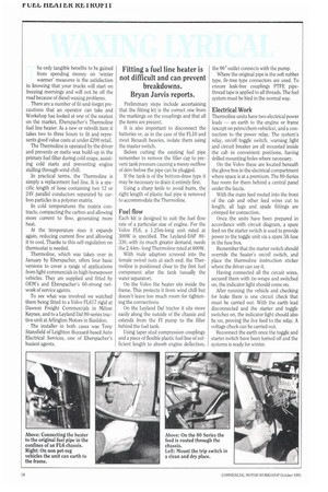
Fitting a fuel line heater is not difficult and can prevent breakdowns. Bryan Jarvis reports.
Page 106
If you've noticed an error in this article please click here to report it so we can fix it.
he only tangible benefits to be gained from spending money on 'winter warmer' measures is the satisfaction in knowing that your trucks will start on freezing mornings and will not be off the road because of diesel waxing problems.
There are a number of fit-and-forget precautions that an operator can take and Workshop has looked at one of the neatest on the market, Eberspacher's Thermoline fuel line heater. As a new or retrofit item it takes two to three hours to fit and represents good value costs at under £200 retail.
The Thermoline is operated by the driver and prevents or melts wax build-up in the primary fuel filter during cold snaps, assisting cold starts and preventing engine stalling through wind chill.
In practical terms, the Thermoline is simply a replacement fuel line. It is a specific length of hose containing two 12 or 24V parallel conductors separated by carbon particles in a polymer matrix.
In cold temperatures the matrix contracts, compacting the carbon and allowing more current to flow, generating more heat.
At the temperature rises it expands again, reducing current flow and allowing it to cool. Thanks to this self-regulation no thermostat is needed.
Thermoline, which was taken over in January by Eberspacher, offers four basic versions to cover a range of applications from light commercials to high horsepower vehicles. They are supplied and fitted by OEM's and Eberspacher's 60-strong network of service agents.
To see what was involved we watched them being fitted to a Volvo FL617 rigid at Dawson Freight Commercials in Milton Keynes, and to a Leyland Daf 80-series tractive unit at Arlington Motors in Basildon.
The installer in both cases was Tony Stansfield of Leighton Buzzard-based Auto Electrical Services, one of Eberspacher's busiest agents. Preliminary steps include ascertaining that the fitting kit is the correct one from the markings on the couplings and that all the items are present.
It is also important to disconnect the batteries or, as in the case of the FL10 and most Renault heavies, isolate them using the master switch.
Before cutting the existing fuel pipe remember to remove the filler cap to prevent tank pressure causing a messy outflow of dery before the pipe can be plugged.
lithe tank is of the bottom-draw type it may be necessary to drain it entirely first.
Using a sharp knife to avoid burrs, the right length of plastic fuel pipe is removed • to accommodate the Thermoline.
Fuel flow
Each kit is designed to suit the fuel flow rate of a particular size of engine. For the Volvo FL6, a 1.25m-long unit rated at 300W is specified. The Leyland-OAF 80330, with its much greater demand, needs the 2.44mlong Thermoline rated at 600W.
With male adaptors screwed into the female swivel nuts at each end, the Thermoline is positioned close to the first fuel component after the tank (usually the water separator).
On the Volvo the heater sits inside the frame. This protects it from wind chill but doesn't leave too much room for tightening the connections.
On the Leyland Dal tractor it sits more easily along the outside of the chassis and extends from the Fl pump to the filter behind the fuel tank.
Using taper stud compression couplings and a piece of flexible plastic fuel line of sufficient length to absorb engine deflection. the 90° outlet connects with the pump.
Where the original pipe is the soft rubber type, fir-tree type connectors are used. To ensure leak-free couplings PTFE pipethread tape is applied to all threads. The fuel system must be bled in the normal way.
Electrical Work
Thermoline units have two electrical power leads — an earth to the engine or frame (except on petro/chem vehicles), and a connection to the power relay. The system's relay, on/off toggle switch, warning light and circuit breaker are all mounted inside the cab in convenient positions, having drilled mounting holes where necessary.
On the Volvo these are located beneath the glove box in the electrical compartment where space is at a premium. The 80-Series has room for them behind a central panel under the fascia.
With the main feed routed into the front of the cab and other feed wires cut to length, all lugs and spade fittings are crimped for connection.
Once the units have been prepared in accordance with circuit diagram, a spare feed on the starter switch is used to provide power to the toggle unit via a spare 3A fuse in the fuse box.
Remember that the starter switch should override the heater's on/off switch, and place the thermoline instruction sticker where the driver can see it.
Having connected all the circuit wires, secured them with tie-wraps and switched on, the indicator light should come on.
After running the vehicle and checking for leaks there is one circuit check that must be carried out. With the earth lead disconnected and the starter and toggle switches on, the indicator light should also be on, proving the live feed to the relay. A voltage check can be carried out.
Reconnect the earth once the toggle and starter switch have been turned off and the systems is ready for winter.