


A New Servo Brake
Page 52
If you've noticed an error in this article please click here to report it so we can fix it.
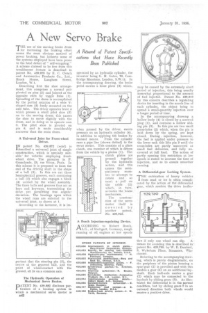
THE use of the moving brake drum for increasing the braking effort seems the most obvious method of power braking, but hitherto some of the systems employed have been prone to the fatal defect of " self-wrapping." A scheme claimed to be free from this troublesome feature is described in patent No. 439,925 by E. C. Clench and Automotive Products Co., Ltd., Brock House, Langhain Street, London, W.I.
Describing first the shoe arrangement, this comprises a normal pair pivoted on pins (2) and jointed at the opposite ends by toggle links (1). Spreading of the shoes is accomplished by the partial rotation of a wide Vshaped cam (3) freely mounted on the axle tube. The driver operates lever 4 which presses a small pilot shoe A on to the moving drum; this causes the shoe to move slightly with the drum, and in doing so to operate cam 3. The pilot shoe is pivoted on pin 6, and is made considerably narrower than the main shoes.
A Universal Joint for Front-wheel Drives.
IN patent No. 439,872 (void) is described a universal joint of simple construction, which is specially suitable' for vehicles employing frontwheel drive. The patentee is P. Granclaude, 23, rue Veron, Paris. In this scheme it is proposed to form the end of the driving shaft in the shape of a ball (2). In this are cut three hemispherical grooves, each containing a ball (3) which also engages a block (9) carried by the wheel assembly. The three balls and grooves thus act as keys and keyways, transmitting the drive yet permitting free angular deviation. The bearings npon which the wheel runs are external to• the -universal joint, as shown at 1.
According to the inventor, it is im portant that the steering pin (5), the centre of the grooved ball, and the point of wheel-contact with the ground, all lie on a common axis.
The Hydraulic Operation of Mechanical Servo Brakes.
DATENT No. 439,882 discloses par
ticulars of a braking system in which a mechanical servo motor as B42 operated by an hydraulic cylinder, the inventor being G. R. Gates, 70, Cambridge Mansions, London, S.W.11. In the accompanying drawing, the brake pedal carries a loose plate (3) which, when pressed by the driver, exerts pressure on an hydraulic cylinder (4), in addition to applying the brakes by manual means. From the cylinder runs a pipe line (shown dotted) to the servo motor. This consists of a plate clutch, one member of which is driven from the vehicle by a pinion (1). The clutch plates are pressed together by the hydraulic action, and this canses the semi stationary member to attempt to rotate and so exert a pull on the cable (2) which, in turn, actuates the brake mechanism.
The construction of the servo motor itself is covered by another patent. No. 439,923.
A Bosch Injection-regulating Device.
AGCORDING to Robert _Bosch, A.G., of Stuttgart, Germany, rough running of oil engines at low speeds
may be caused by the extremely short ' period of injection, this being usually somewhat proportional to the. amount of fuel injected. Patent No. 439,919 by this concern describes a regulating device for inserting in the nozzle line of each cylinder, the object being to spread a small-quantity injection over a longer period of time.
In the accompanying drawing a hollow body (4) is closed by a screwed plug (1), and contains a hollow sliding pin (3). In this pin are two small cross-holes (2) which, when the pin is held down by the spring, are kept closed. During., injection, however, the fuel is applied under pressure to the lower end; this lifts pin 3 until the cross-holes are partly uncovered at small fuel deliveries, and fully un
covered at full load. The 'action of partly opening this restriction at low speeds is stated to increase the time of injection, and so to ensure smoother running.
A Differential-gear Locking System.
THE extrication of heavy vehicles from mud or ice is often complicated by the action of the differential gear, which renders the drive ineffec tire if only one wheel can slip. , A means for avoiding this is described in:patent No. 439,790, by W. E. Danford, 8, Wykeham Place, Stanmore, Winchester.
Referring to the accompanying drawing, which is purely diagrammatic, on the periphery of the pinion housing a spur-gear (I) is provided and with this meshes a gear (4) on an additional layshaft. Each half-axle carries a gear (2) which may be connected to the layshaft by sliding gears (3). As illustrated the differential is in the normal condition, but by sliding gears 3 in an outward direction both wheels would receive a positive drive.