


New Efficiency-promoting Equipment
Page 37
If you've noticed an error in this article please click here to report it so we can fix it.
PROGRESS in chassis design depends largely upon detail improvements, these being reflected in enhanced performance, greater durability and cheaper production. A number of items of equipment, constituting examples of this form of advancement, has recently been developed by Feeny and Johnson, Ltd.; 134-136, Ealing Road, Wembley, Middlesex.
Specially noteworthy amongst these is a new steering unit, incorporating a worm of unusual construction which possesses many attractions. Its outstanding feature is that the worm, instead of being machined from the solid, is built up from two parts—a thread and a shaft.
The former resembles a helical spring and is fixed to the shaft by dogs engaging, with a collar at the upper end, that is the end extended to form the steering column. At the lower extremity there is an adjusting nut, provided with a locking device; by tightening this, the pitch of the worm can obviously be reduced.
The advantages claimed for this system of construction include cheapness of manufacture, a cushion drive, cad the fact that wear can be taken up by adjusting the nut. The worm engages with a spherical peg on the d.rop-arm lever, and the worm housing serves also as a bearing, provision for thrust being made independently.
A minimum of relative movement of the inner to the outer member, is the feature of the latest Feeny and Johnson vacuum-servo-brake valve. The travel has been reduced to no more than 5-64 in. Despite this short stroke and, inevitably, quick action, the valve is progressive in operation. It is suitable for inclusion in either a compression or tension rod from the pedal.
Differing considerably from the earlier design, the new valve, in the case of the pull-on type, is rendered air-tight, when in the normal closed position, by a cone face. Pressure on the pedal lifts the valve from its seating, but does not open the port until a parallel part has been withdrawn, as with a masked-type engine valve. Also, until the parallel portion is clear of the seating,, the bellows is open to atmosphere. . . The efficient working of the valve appears to depend largely upon the synchronizing of the opening of the valve to vacuum with the cutting off of the atmospheric aperture and upon the clearances between the effective parts.
Operating one of these valves by hand, without leverage or any manipu 'alive equipment, we were able to control to a nicety the lifting of 2 cwt. by a standard bellows.
In designing servo gear for existing brake layouts, consideration has obviously to be paid to the distance of travel and the pull of the bellows. To avoid alteration of the linkage, etc., the dimensions of the bellows must be varied appropriately.
With the object of diminishing to three the number of standard bellowsdiameters necessary, Feeny and Johnson, Ltd., has evolved a system by which the bellows are formed in sections of one fold each, so that any desired length can be built up. The joints are made with two hacking rings, which grip the bellows flanges and are held together by hollow rivets.
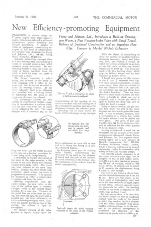
A fourth new product of this concern is the F. and J. universal hose clip. For small vacuum connections, or large water joints, these clips are variable to suit any diameter from in. upwards. An accompanying drawing shows how the device functions. There arc three parts—a hand which encircles the hose twice, a buckle to which one end is attached, and a rotable pin which is split to receive the slack end, and on which the band is wound.
Being of square section, the pin cannot turn under the pull of the baud, because one face bears against the inner coil. It can be rotated, however, with a screwdriver or a tommy bar, whilst for quick release it can be pulled out with pliers. One gross of pins and buckles with 144 feet of strip costs 34s. and is sufficient for the same number of 1i-in.-diameter clips, Having experienced a need for an exhauster, for use as part of the brake equipment of oil-engified chassis, Feeny and Johnson, Ltd., has acquired distributing rights for a new product Of Nichols Compressors, Ltd., 303-304, Finsbury Pavement House, London, E.C.2, a concern well known in general engineering circles in connection with rotary blowers and vacuum pumps, The Nichols vehicle exhauster is of the vaned eccentric-rotor type, and is designed to run at half engine speed. At 1,165 r.p.m. it is capable of generating 29 ins, of vacuum, whilst at 250 r.p.m. 10 iris, of vacuum can be raised in 11 seconds, the displacement being 4 cubic ft. per minute.
The body of the device is of cast-iron, and the tunnel dimensions are 4 ins. by 4+ ins. There are four vanes, -Ain. thick, made of high-quality steel, and set in the cast-iron rotor at right angles to each other. Between opposite .6.nes are push-rods by which the receding motion of one vane is imparted to the other, thus pushing it out.
By this means alone, it is clear that the vanes cannot be held in continual contact with the walls of the tunnel in which they revolve, but it is claimed that the initial movement thus given enables centrifugal force to do the rest, and• to the puSh-rod arrangement is attributed the efficiency of the exhauster at speeds as low as 200 r.p.m.