


Universal Joint for a Front-wheel Drive
Page 32
If you've noticed an error in this article please click here to report it so we can fix it.
A Resume of, Recently Published Patent Spec ific a lions
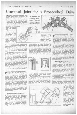
DRIVEN wheels which are also steerable present many problems in the design of universal joints, and an attempt to arrive at a solution is disclosed in patent No. 475,455 by J. A. Parent, 164, rue de Courcelles, Paris. The object of the scheme is to produce a joint capable of considerable angular deflection, which can reach or even exceed 75 degrees from the primary shaft,
The accompanying drawing shows one view of the
mechanism, although the action is not easy to follow from this alone. The shaft (10) is the driving member, and it carries a crosspin (6) which drives a trunnion-ring
(7). The cross-pins (not shown) at right-angles to pins 6 are journalled in bosses formed in the outer enclosing shell (1): all the foregoing is duplicated on the side of the driven shaft (5).
To locate the intersection of the two shaft axes, a ball-and-socket joint (3) is used, this being formed of two members (2 and 4) each housed in a bore in one of the main shafts. Each spindle is journalled on roller bearings, the one on the right being additionally fitted with a hall-thrust (8) on account of end-pressure from a spring (9), The' object of the roller bearings is to allow the ball-joint assembly to remain stationary while the rest revolves; this is rendered necessary by the partly enveloping shape of the outer sphere.
Improved Injection-pump Control.
PNo. 475,390, dealing with modifications in the admission and release arrangements of injection pumps, comes from 0. Yamashita, of Jotoku, Tokio, Japan. The object of the invention is to prevent the forma. tion of vacuum in the working space, and to provide a one-way path for the " spilled " fuel. The drawing shows the proposed valve arrangement, comprising three one-way valves, an inlet (1), a discharge valve (2), and a valve (3) for the pressure release. The moment of release is controlled, in the well-understood manner, by a helical edged plunger.
Trailer with a Variable Height.
ANAME associated with progressive design, that of N. Straussler, appears, in conjunction with AlvisStraussler, Ltd., Coventry, in patent No. 475,232. which discloses an unorthodox layout for an adjustable
height trailer. Although designed primarily for the 'transport of aircraft bombs, the scheme is, nevertheless. capable of a wider • application. A striking point is the use of a single backbone of I or 'r. sectionfor the frame; this by rea son of its flexibility, enables all wheels to remain in ground contact over rough surfates. The drawing shows the unusual suspension system, comprisimg a pivoted link (9) in conjunction with a leaf spring, a scheme which ensures a constant angle between the axis of the main frame and the king pin which passes through the centre of the front axle. The assembly forms a parallel motion, the spring merely replacing what would otherwise be a rigid link.
The suspension forces are opposed by an hydraulic cylinder and piston (1) which, if released, allows the frame to sink until arrested by an abutment (2) reaching a frame bracket, by which time the link (3) is substantially horizontal. German Heat-conserving Piston.
TO avoid overheating alloy pistons, and at the same time to conserve combustion heat, are the objects of a piston design .disclosed in patent No. 474,969 by Junkers Flugzeug-undMotoren-Werke A.G., of Dessau, Anhalt, Germany.
The piston comprises a light-alloy skirt and subhead, to which is attached an arch-section cast-iron crown (1). Vertical bosses (3) are cast in the skirt to prevent distortion by the long bolts holding on the iron head, and these bolts are fitted in clearance bores to allow the head to distort under heat. The distortion takes the form of rising in the centre, which still further reduces the area in contact with the alloy portion. The bead performs the additional duty of clamping the special non-split piston ring (2).
Making for Easier Discharge in Refuse Collectors.
IMPROVEMENTS in the design of lrefuse collectors form the subject of patent No. 474,453 by C. K. Edwards and Slielvoke and Drewry, Ltd.. Letchworth, Herts. The object of the invention is to minimize the space required when discharging the load, a point of some importanCe because refuse destructors are not usually constructed to allow of any great overhang of the discharging vehicle.
The drawing shows the vehicle in the discharging position. The basis of the patent is the construction of the rear door of the body ; this consists of two portions, an upper piece (4) and a lower flap (2). These are hinged about a pivot (3) and can be folded, as the body lifts, into t h e position shown, by a cable. The structure (1) is described as an
hydraulic ramming device and loading hopper; this is also lifted clear when the body is tipped. The main features of the design are covered by an earlier. patent. No. 424,396.