


A Centrally Pivoted FRONT-AXLE ARRANGEMENT
Page 66
If you've noticed an error in this article please click here to report it so we can fix it.
MHE name of Henry Garner, which has already been associated with many useful improvements in motor design, appears in connection with Patent No. 321,934, which relates to the mounting of the front axles of such vehicles as those intended to be used in countries where there are no proper roads, and particularly in the case of vehicles for military use. In such machines it has been found necessary to provide some means whereby the front axle can tilt so as to accommodate itself to uneven ground. It may be said that good springs will permit sufficie it movement for this purpose, but many who have bad actual efperience in such countries hold that some form of central-pivot arrangement for the front axle is an absolute necessity, as it relieves both chassis and body from undue strains, and at the same time allows all wheels to remain in contact with the ground, no matter how uneven.
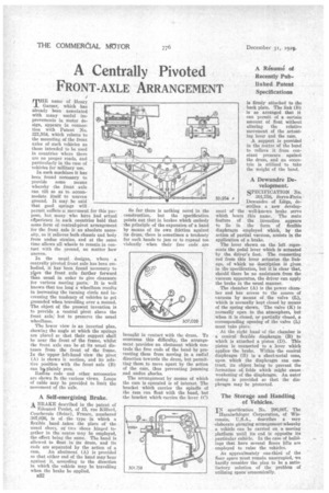
In the usual designs, where a centrally pivoted front axle has been embodied, it has been found necessary to Wee the front axle farther forward than usual in order to give clearance for various moving parts. It is well known that too long a wheelbase results in increasing the turning circle and increasing the tendency of vehicles to get grounded when travelling over a mound. The object of the present invention is to provide a central pivot above the front axle, but to preserve the usual wheelbase.
The lower view is an inverted plan, showing the angle at which the springs are placed so that their support shall be near the front of the frame, whilst the front axle can be at its usual distance from the front of the frame. In the -upper left-hand view the pivot (A) is shown ii section, and its relative position with the front axle (B) can bo plainly seen. Radius rods and other accessories are shown in the various views. Loops of cable may be provided to limit the movement of the axle.
A Self-energizing Brake. A BRAKE described in the patent of
Edouard Poulet, of 15, rue Kilford, Courbevoie (Seine), France, numbered 307,026, is of the type in which a flexible band takes the place of the usual shoe-3, or two shoes hinged together in the centre may be employed, the effect being the same. The band is allowed to float in its drum, and its ends are separated by the action of a cam. An abutment (A) is provided so that either end of the band may bear against it, according to the direction in which the vehicle may be travelling when the brake be applied.
3332 So far there is nothing novel in the construction, but the specification points out that in brakes which embody the principle of the expansion of a band by means of its own friction against its drum, there is sometimes a tendency for such bands to jam or to expand too violently when their free ends are btought in contact with the drum. To overcome this difficulty, the arrangement provides an abutment which controls the free ends of the band-by preventing them from moving in a radial direction towards the drum, but permitting them to move apart by the action of the cam, thus preventing jamming and undue shocks.
The arrangement by means of which the cam is operated is of interest. The bracket • which carries the spindle of the cam can float with the band, but the bracket which carries the lever (C) is firmly attached to the back plate. The link (B) is so arranged that it can permit of a certain amount of float without altering the relative movement of the actuating lever and the cam. A support is provided in the centre of the band to relieve it from constant pressure against the drum, and an eccentric is utilized to take the weight of the band.
A Dewandre Development.
SPECIFICATION No. 301,758, Servo-lTrein Dewandre of Liege, describes a new development of the well-known brake servo which bears this name. The main feature of the invention appears to lie in the form of flexible diaphragm employed which, by the action of partial vacuum, assists in the application of a brake. The lever shown on the left represents the pedal lever which is actuated by the driver's foot. The connecting rod from this lever actuates the linkage, of which no description is given in the specification, but it is clear that, should there be no assistance from the vacuum apparatus, the driver can apply the brake in the usual manner.
The chamber (A) is the power chamber and has access to the source of vacuum by means of the valve (L), which is normally kept closed by means of the spring shown. The valve (K) is normally open to the atmosphere, but when it is closed, or partially closed, a corresponding opening of the valve (L) must take place.
At the right hand of the chamber is a conical flexible diaphragm (B) to which is attached a piston (D). This piston is connected to a lever which applies the brake. Within the conical diaphragm (B) is a sheet-metal cone, upon which the diaphragm can contract, its object being to prevent the formation of, folds which might cause weakening of the diaphragm. An outer casing is provided so that the diaphragm may be protected.
The Storage and Handling of Vehicles.
IN specification No. 296,007, The Harnischfeger Corporation, of Wisconsin, 'U.S.A., describes a very elaborate garaging arrangement whereby a vehicle can be carried on a moving Platform until its end is opposite its particular cubicle. In the case of buildings that have several floors lifts are employed to raise the vehicles. As approximately one-third of the floor space must remain unoccupied, we hardly consider the plan to be a satisfactory solution of the problem of utilizing spaceeconomically.