


An Oil Seal for Running Shafts
Page 42
If you've noticed an error in this article please click here to report it so we can fix it.
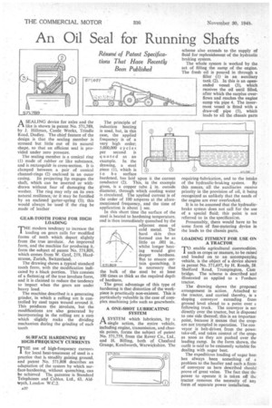
ASEALING device for axles and the like is shown in patent No. 571,789, by J. Hillman, Castle Works, Trindle Road, Dudley. The chief feature of the design is that the sealing member is stressed but little out of its natural shape, so that an efficient seal is provided under zero pressure.
The sealing member is a conical ring (1) made of rubber or like substance, and is rectangular in cross-section. It is clamped between a pair of conical channel-rings (2) enclosed in an outer casing. Its projecting lip engages the shaft, which can be inserted or withdrawn without fear of damaging the washer. The ring may rely on its own natural resilience; or it may be fortified by an enclosed garter-spring (3); this would always be used if the ring be made of leather GEAR-TOOTH FORM FOR HIGH LOADING
THE modern tendency to increase the loading on gears calls for modified forms of teeth which depart slightly from the true involute. An improved form, and the machine for producing it, form the subject of patent No. 571,809, which comes from W. Graf, 219, Hardstrasse, Zurich, Switzerland.
The drawing shows a typical standard tooth form, with the modification indicated by a black portion. This consists of a flatteniag of the title involute form, and it is claimed to reduce the tendency to impact when the gears are under heavy load.
The machine described is a generating grinder, in which a rolling arc is controlled by steel tapes wound around it. This produces the involute, but the modifications are also generated by incorporating in the rolling arc a cam which slightly rocks the dividing mechanism during the grinding of each tooth SURFACE HARDENING BY HIGH-FREQUENCY CURRENTS
THE use of high-fiequency currents for local heat-treatment of steel is a practice that is steadily gaining ground, and patent No. 571,808 describes an adaptation of the system by which surface-hardening, without quenching, can be achieved Tht patentee is Standard Telephones and Cables, Ltd., 63. Aldwych, London W.C.2.
The principle of induction heating is used, but, in this case, the applied frequency is of a very high order; 5,000,000 cycles per second is quoted as an example. In the drawing, a steel piece (I), which is to be surface hardened, has laid upon it the current conductor (2). This, in the example given, is a copper tube in. outside diameter, through which cooling water is circulated. The applied current is of the order of 100 amperes at the aforementioned frequency, and the time of application is about 1sec.
In this short time the surface of the steel is heated to hardening temperature, and is then immediately quenched by the adjacent mass of cold metal. The hard skin thus formed can be as little as .001 in., whilst longer heating would give deeper hardness. But to ensure certain quenching, it is necessary that the bulk of the steel be at least 100 times as thick as the required depth of hardness.
The great advantage of this type of hardening is that distortion of the workpiece is practically non-existent. This is particularly valuable in the case of complex machining jobs such as gearwheels.
A ONE-SHOT LUBRICATING SYSTEM
ASYSTEM which lubricates, by a single action, the entire vehicle, including engine, transmission, and chassis points, forms the subject of patent No. 571,759, from the Rover Co., Ltd., and H. Billing, both of Chesford Grange, Kenilworth, Warwickshire. The
scheme also extends to the supply of fluid for replenishment of the hydraulic braking system.
The whole system is worked by the act of filling the sump of the engine. The fresh oil is poured in through a filler (1) in an auxiliary tank (2). In this is an openended vessel (3), which receives the oil until filled, after which the surplus overflows and reaches the engine sump via pipe 4. The innermost vessel is fitted with a draw-off pipe (5), which leads to all the chassis parts requiring-lubrication, and to the intake of the hydraulic-braking system. By this means, all the auxiliaries receive priority in the provision of oil, it being recognized as unlikely that the needs of the engine are ever overlooked.
It is to be assumed that the hydraulicbrake system does not call for the use of a special fluid; this point is not referred to in the specification.
Presumably, there would have to be some form of fine-metering device in the leads to the chassis parts.
LOADING FITMENT FOR USE ON A TRACTOR
TO enable agricultural commodities, such as crops or manure, to be raised and loaded on to an accompanying vehicle, is the object of a device shown in patent No. 571,697, by H. Roads, 58 Shelford Road, Trumpington, Cam bridge. The scheme is described and illustrated as applied to a Fordson tractor.
The drawing shows the proposed arrangement in action. Attached to the tractor, and carried thereby, is a sloping conveyor extending from ground level ahead to a point over a following truck. The conveyor is not directly over the tractor, but is disposed to one side thereof; this is an important point, because it means that the crops are not trampled in operation. The con veyor is belt-driven from the powe; take-off, and takes control of the crops as soon as they are pushed over the leading ramp. In the form shown, the outfit is said to be eminently suitable foe dealing with sugar beet.
The expeditious loading of sugar beet has always been something of a problem to the haulier and such a form of conveyor as here described should prove of great value. The fact that the power to operate it is taken off the tractor removes the necessity of any form of separate power installation.