


Patents Completed.
Page 20
If you've noticed an error in this article please click here to report it so we can fix it.
TRACTORS.—Crompton.---No. 7,489, dated 26th March, 1910.—This invention relates to road locomotives or to tractors, and has for its object an improved arrangement of fairlead pulley for use in connection with the winding or hauling mechanism for such vehicles. This fairlead pulley is mounted on the rear of the framework of the vehicle in a substantial frame, having a hollow pivot pin through which the winding
or hauling rope passes. The pivotal axis is in the central longitudinal axis of the chassis of the tractor and is parallel with the hauling line of the vehicle. In order to allow the pulley to be large enough, the frame in which it is supported is bent downwards so that the groove in which the wire rope lies coincides with the pivotal axis. It will be seen that this pulley is mounted similarly to a castor on a chair, but is horizontal instead of vertical. In cases where the roping conditions necessitate the rope-s being given a half-turn round the fairlead pulley and carried forward from the tractor, it is necessary to give the framework carrying the pulley some other support, and this is obtained by using sprags as struts which engage with the frame to form a triangular strutted frame. The arrangement allows the fairlead pulley to be turned to give a pull in any direction from the tractor.
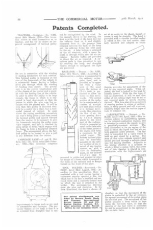
CARRIAGE LAMP.—J. and R. Oldfield, Ltd.—No. 4,712, dated 25th Februars . 1910.—This invention comprises improvements in lamps such as are used on automobiles and carriages. The particular feature of the lamp is that it is so screened from draughts that it can
not be extinguished by the wind. lii the example shown in the drawing, the door is at the back of the lamp and has the reflector fixed on it and slightly separated from it ; the passage thus obtained between the back of the lamp and the reflector forms the inlet path for the air. A false bottom is arranged on the oil reservoir, with a space beneath it through which also the air cir
culates. Suitable baffles are provided to direct the air as required. A circuitous path is thus presented to any air entering the lamp, and draughts violent enough to extinguish the light are prevented.
RADIATOR. — Deacon. — No. 6,891, dated 18th March, 1910.—According to this invention a radiator is constructed in the ordinary rectangular form, and is provided at its upper end with a water tank of the usual type ; the bottom of this tank is perforated to allow the water to drip downwards. The central portion of the radiator is constructed of a number of straight and bent plates which a r e inclined downwards, thus directing the flow of air, the water passing down by th es e sloping plates to the lower part of the radiator, which is connected as usual to the inlet side of the water jacket of the engine and forms a receptacle for the cooled water. The bottom inclined plate may be removably mounted on the radiator to allow of the re. moval of any foreign matter, or, with a view to facilitating pairs, all the inclined plates may be mounted in guides and secured in place by means of a frame which is secured to the walls of the radiator and to flanges formed on the front of the plate.
TOOfs HOLDER.—Rosenbeck.—No. 19,587, dated 22nd August, 1910.—According to this specification, there is combined with a tool carrier having a transverse angular opening a disc tool which has in its face a bevelled and serrated recess and a similarly-formed stud by which the tool is attached to the holder. The accompanying drawings chow the plan and elevation. In the form illustrated, the head is shown off set at an angle on the shank, though of course it may be straight. The head is provided with a circular bevelled socket in which it fits ; the tool carrier, similarly bevelled and adapted to rotate therein, provides for adjustment of the tool to any required angle. When adjusted, the tool is locked in the head by suitable screws. With the disc type of tool as illustrated, it will be seen that either of the cutting edges may be set at any required angle by merely rotating the tool. This form also gives an amount of wearing surface in excess of ordinary tooLs, is easily ground and will wear considerably longer than the various types of tools in common use.
CARBURETTER. — Nowson. — No. 26,529, date a 14th April, 1910.—This invention relates to carburetting apparatus for internal-combustion engines, and is intended to control the supply to give a practically-constant mixture. The form illustrated is for an engine of the type in which the liquid fuel and air are both supplied under pressure. The fuel inlet is controlled by a valve which is held up and closed by a spring. The stem of this valve extends upward past lateral jets and through a suitable gland into the mixing chamber. Adjacent to the mixing chamber is a cylinder in which is-fitted a piston valve, the lower end of this chamber is placed in communication with the high-pressure air
chamber, so that the movement of the piston is controlled by the air pressure, the upward movement of the piston opens the air-inlet port. The movement of this piston actuates a lever which in turn opens the fuel-inlet valve, so that the opening of the fuel valve is controlled by and is proportional to the opening of the air-inlet valve.