


Battery-electric Has Separate Clutch
Page 58
If you've noticed an error in this article please click here to report it so we can fix it.
TMPROVEMENTS in the design of
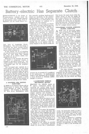
battery-electric vehicles . form the subject of patent No. 626,820 (delayed in publication), which comes from F. Richfield, and the Austin Motor Co., Ltd., both of Longbridge Works, Birmingham_ The aim of the design is to przvent the heavy starting current which always flows when a stationary motor is first switched on.
In this scheme, the act of switching on runs the motor up to speed under no load, the load being then applied by means of an electric clutch, controlled by the driver.
Referring to thedrawing, the motor (1), which is compound Wound, is coupled to the electric clutch (2). The output member of the clutch drives via a two-speed gear (3), the Propellershaft (4).
The two-speed gear operates in a noi,e1 manner, the choice of ratio being governed by the load on the vehicle. A spring (5) normally keeps the gearlever in the high-gear position, but if the vehicle be heavily loaded, the lever is pulled into low gear by a solenoid (6). The solenoid circuit contains a switch (7) which is worked by the position of the suspension springs of the vehicle.
A MACHINE FOR TESTING INJECTORS
USERS of oil-engined vehicles will be %—lintercsted in patent No. 629,681, which discloses an outfit for testing injectors. The inventor, L. Hartridge, 26, West Street, Buckingham, states
that, generally speaking, hand-operated testers are unreliable, as the pressure applied thereby is jerky and uncertain. The device shown is power-driven, and can be adjusted to conform to a standard rate with accuracy.
Referring to the drawing, an electric motor drives, through reduction gearing, a cam (1) which works the plunger of an injection pump (2). The pump supplies the injector (3) under test, .subject to a cut-off valve and a quantity contfol, both operated by external handles (4 and 5). A gauge (6) is provided to indicate the applied pfessure.
An air-ekhausting fan (7) creates a draught through the receiver funnel (8) to prevent loss of fuel. A pressure accumulator (9) enables a pressureholding test to be applied with the pump stopped; if the injector holds the pressure for 10 seconds it is considered to be satisfactory. A hand-operated model is also described, but it includes a heavy flywheel to eliminate sudden changes in pressure.
A PASSENGER VEHICLE RECORDING DEVICE
DATENT No. 628,979, shows an
electro mechanical device for recording the various items in the operation of a passenger-service vehicle, the patentee being P. Meuriot, Paris. The machine records the number of passengers alighting and boarding, the number of stops and the distance between them. It can also be made to give totals if required_
The drawing shows the electric circuit and a section of the platform step, which-is the " brain " of the apparatus. The first step (1) is liermitted to have a small horizontal movement whin, in one direction; closes contact points (2). and in the. other direction another set of contacts (3).
In the act of boarding,, the passenger closes frrst one circuit and then the other, whereas when alighting, the order of closing is in the reverse direction. The contacts operate markers. (4) on a
moving ribbon of paper, and by-examining the sequence of the mark% it is
possible to tell whether the passenger was entering or leaving.
Stopping of the vehicle is recorded by means of a centrifugally operated switch (5) driven like a speedometer. This breaks the main circuit when the vehicle inovess so that the length of blank paper indicates the running time. The paper is driven by a clockwork mechanism (6) which can, if required, print time intervals. The mechanism for giving the totals is not shown, but consists of a simple electric counter. TWO-STROKE ENGINE EMPLOYS
PETROL INJECTION
ANEW type of two-stroke engine comes in patent No. 629,205, from S.A. des Usines Chaussott, Asnieres, France. The design is claimed to be efficient mainly on account of it being impossible for any fuel to escape through" the exhaust ports.
Referring to the drawing, a. blower (1) constantly pumps air into a chamber
(2) where it awaits admission via a piston-controlled port (3). An exhaust port (4) is also pistoncontrolled in the usual way. Above the head is a chamber (5) closed by a cam-operated valve (6). Petrol or other light fuel is con stantly s i stantly forced into t at a controlled rate by a gear-pump (7).
The cycle is as follows: from top dead-centre the piston descends and uncovers the exhaust port, followed rapidly by the uncovering of the air port, so that a straightthrough scavenge is obtained. As the piston ascends, the ports are closed, and then the poppet valve in the head is opened.
The upper chamber being filled with air plus fuel, a rich charge is projected into the cylinder air to make a mixture of the correct strength. The piston then rises oh a normal compression stroke, but just before the firing
stroke, the head-valve closes, so that a portion of the mixture is stored for use onthe next stroke, after it has been enriched 'by the constant inilsw of fuel from the gear pump_ The charge is ignited by a sparking plug in the usualWay. ,A feature of the patent is the use of a helically grooved valve-passage, the ,effect being to impart "a. whirl to the incoming fuel charge.