


UNEQUAL DISTRIBUTION OF BRAKE POWER:
Page 30
If you've noticed an error in this article please click here to report it so we can fix it.
A Resume of Recently Published Patent Specifications.
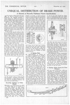
ANY invention which bears the name F. H. Royce is always of interest. Application No. 225.031 describes a weans adopted by which the necessary greater braking power can be applied to the rear brakes, while slightly less power is applied to the front-wheel brakes.
The device which accomplishes this serves also as an efficient compensator. This arrangement is described as being equally useful whether operated by means of foot or hand levers, or whether actuated by means of a servo mechanism. Compensators have been made which resemble an ordinary bevel-wheel type of differential gear.
, In the present case the action is similar, EO far as the balance of power goes, but the distribution is unequal, owing to the fact that, in place of the usual bevel wheels, which would be of equal diameter, a Fun wheel and an annular wheel are employed which are of unequal diameters. The view shows the arrangement in section, and it will be seen that the lever (A) is keyed to the plate (Al), on which are mounted the studs which carry the planet wheels (Al). The annular gear (B) has a sleeve attached to it, on which is keyed the lever (B1). The sun wheel (C) is keyed to the shaft on which it is mounted, and so is the lever (CI). It will be seen that when power, either from the foot, or hand, direct or through the servo mechanism, is applied to the lever (A), it sc.ts up a rotary motion in the plate (Al) and carries with it the pinions. The pinions moving bodily round the axis of the shaft cause the aim wheel and the annular wheel to move in the same direction. According to the different diameters of these wheels, so will the power be distributed between the front and back-wheel brakes.
Securing Springs to Valve Stems.
THERE is no method known by which
a spring collar can be secured to a Naive stem without, to some extent, weakening the stem. The object of the invention of Sydney Smith and A.C. Cars, Ltd., No. 225,064, is to provide a means whereby such collars may be secured to valve stems with the minimum of weakness to that part. The illustrations will show plainly that the stem of the valve has a number of grooves cut along it in a direction
1148
parallel to its axis. A collar is formed so that its inner surface has projections which correspond in shape to the grooves in the valve stem. The outer part of this collar is turned taper, as shown, and after being formed, it is cut into three sections. An outer collar is provided with a bore corresponding in taper to the inner collar. It will be seen that the pressure of the spring tends to close the inner collar on to the valve stem, thereby setting up considerable friction, which helps to keep all parts tight. We have seen a split collar surrounded by an outer collar used for the same pur pose before, but in that case a groove was turned in the valve stem at the part gripped by the split collar. The point of novelty in the present invention appears to exist in replacing a circumferential groove by a number of longitudinal grooves.
A Spring Hub.' G BROULHIET, of France, de scribes in application No. 218,256 a hub which is claimed to act as a spring, and so to absorb road shocks. From a very long and wordy sirecification we gather that this., invention consists of an inner hub (A) and an outer shell (B), which carries the spokes forming the wheel. A spring mechanism has the effect of centring the wheel on the inner hub, and we take it that this is intended to be the position of the wheel when running on a smooth road. The inner hub (A) is provided with a large flange, which gives steadiness to the wheel. A member (C) is free to slide on the body of the inner hub, and is provided with a ball race of special form, which is centred in (C) by means of a groove, as shown. A similar ball race is mounted in a groove in the outer hub (B). A spring and collar on (A) provide a pressure between the member (C) and through it to the ball race and through the balls and the other ball race and the internal flange of the outer hub (B) against a collar of some suitable substance to the flange of the inner heb. By this pressure the wheel is kept always at right-angles with the axis of the axle. It will be 'seen that, should the wheel meet an obstruction on the road which places an unusual stress on it in a direction at right-angles to the axle, the balls will allow the ball races to be forced apart, and the outer hub to become momentarily eccentric to the inner hub, and so relieve the shock. The disc which separates the two flanges is described as setting up a snubbing friction. The balls and races shown here are not those which act when the wheel is revolving in the ordinary way, as the inner hub is apparently supposed to run on bearings on its axle. The specification vaguely refers to the drive of the hub by means of friction, but no mention is made of its use on a rear axle or how the drive can be transmitted from an axle to a wheel that is not constantly concentric. This point is the stumbling block which has been met by roost inventors of spring wheels. If we are not mistaken, something very sim;lar was tried in the bicycle many years ago. In that case, however, a meana was provided for transmitting the drive to the rear wheel.
A Spring which Forms Its Own Damper.
IT may seem curious that, while one
inventor is introducing anti.friction devices between the leaves of springs for the purpose of increasing their activity, other inventors should be making devices which have the opposite effect. In the invention of F. L. Eiroussouse' of France, No. 219,012, the leaves of the spring have a slight set at their outer ends, which is shown on the left of the upper view. When assembling the spring, pressure is brought to hear on the ends, and while under pressure the clips are fixed up as shown on the right.