


• AUXILIARYE INE SCHEME FOR ENHANCING E( \TOMIC OPERATION
Page 30
Page 31
Page 32
If you've noticed an error in this article please click here to report it so we can fix it.
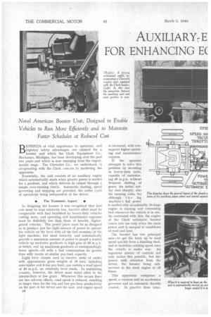
Novel American Booster Unit, Designed to Enable Vehicles to Run More Efficiently and to Maintain Faster Schedules at Reduced Cost Output of Main Engine Amplified by a Second Engine, Which is Started, Regulated and Stopped by Wholly Automatic Means BENEFITS of vital importance to operators, and highway safety advantages, are claimed for a booster unit which the Clark Equipment Co., Buchanan, Michigan, has been developing over the past two years and which is now emerging from the experimental stage. The Chevrolet Co., we understand, is co-operating with the Clark concern in marketing the apparatus.
Essentially, the unit consists of an auxiliary engine which automatically starts when greater power is needed for a gradient, and which delivers its output through a simple over-running clutch. Automatic starting, speed governing and stopping are provided, the entire cycle of operations being independent of the driver.
0 The Economic Aspect • In designing the booster it was recognized that first cost must be kept relatively low, tractive effort must be comparable with that furnished by heavy-duty vehicles costing more, and operating and maintenance expenses must be definitely less than those of heavier, higherpriced vehicles. The power plant must be so designed as to produce just the right amount of power to operate the vehicle on the level with all the fuel economy of the light machine, but must instantly and automatically provide a maximum amount of power to propel a loaded vehicle up moderate gradients in high gear at SO m.p.h. or better, and up maximum gradients at correspondingly lower speeds—all with a fuel consumption no greater than with trucks of .similar pay-load capacity.
Light lorry chassis used as tractive units of outfits with approximate gross weights of 10 tons, including semi-trailer and 6-ton pay-load, can sustain a road speed of 90 m.p.h. on relatively level roads. In undulating country, however, the driver must resort often to the intermediate or low gears. Whenever this occurs there are two adverse effects, road speed is reduced, resulting in longer time for the trip and less per-hour productivity on the part of the driver and the unit, and engine speed s4 is increased, with consequent higher operating and maintenance expense.
If the operator attempts to solve this problem by investing in heavy-duty units, capable of maintaining 40 m.p.h. without frequent shifting of gears, his initial outlay rises Sharply, also his running costs, for although t h e big machine's full power is needed only occasionally, its large engine is running arid consuming fuel whenever the vehicle is in use. As contrasted with this, the engine of the Clark automatic booster comes into use only when the main power unit is unequal to conditions of road and load.
The booster, has two principal uses—to get the lorry up to road speed quickly from a standing start, and to maintain cruising speed once the vehicle is under way. An ingenious system of controls not only makes this possible, but dispenses with attention from the driver, the booster being subservient to the main engine at all times.
•
This apparatus comprises a _speed, a vacuum and an accelerator governor and an automatic throttle control. In practice these inter
related units work together to start, control and stop the booster engine and assure a smooth, positive flow of power from it to
t h e transmission, when, and only when, the need for extra power exists.
Each phase of the booster's operation is automatic and instantaneous, the entire cycle being completed in a fraction of the• time it takes to describe it. However, for those interested in its detailed workings the following description is given. Setting out with a heavy load, for instance, and desiring to get up to cruising speed quickly, the driver starts in first gear and shifts into second quite namally. So soon as about 6 m.p.h. is reached the speed governor comes into use automatically and closes a .contact, which renders the booster engine's starting and ignoltion systems ready for action.
Conditions have now heen set up so that in accelerating through second gear there is a drop in pressure in the main engine's intake manifold. This closes the vacuum switch and the booster engine will start. With full throttle on the main engine, the accelerator pedal is, of course, completely depressed, which closes the booster's accelerator switch and electrically opens its throttle. The booster speeds up and, through its overrunning clutch, delivers its power—as regulated by the main engine's own accelerator—to 'assist the main engine.
This enables the driver to accelerate rapidly to a governed speed in second gear, at which time he removes his foot from the accelerator allowing both engines to slow down. He then shifts into third gear and, by means of the accelerator, brings both engines up to maximum third-gear power, accelerating through this range to the governed third-gear speed. The same cycle is repeated on the shift to direct drive.
Once top gear is engaged the booster delivers its power to assist the main engine until the vehicle reaches 40 mph., whereupon the speed control opens, the boaster's ignition circuit and stops the engine. This action automatically re-sets the vacuum switch and leaves everything ready for the next start. All this, as stated before, takes place automatically and each step is instantaneous, so that the sum total is a smooth, uninterrupted cycle.
• Important Control Detail • The vacuum switch, once it has performed its function of starting the booster engine, is locked out of operation until the vehicle reaches cruising speed. During the interim the booster is governed solely by the speed control. This provision assures proper functioning through second and third gears, regardless of fluctuations in the main engine's speed in the process of getting into direct gear.
Provision of both speed and vacuum-control switches restricts the operation of the booster.-.-once the vehicle is in direct gear—to those times when the main engine is unequal to the job. Without both controls, it would be possible to cut-in the booster at any predetermined speed without using the full power of the main engine. The booster's principal function, maintenance of cruising speeds on the road, is performed whenever the vehicle encounters a gradient which causes it to slow down, even with wide-open throttle, to 31 m.p.h. During such deceleration the vacuum switch is closed, but the speed governor does not come into operation until speed is reduced as stated. At that point the booster engine is automatically started. It delivers its power to the vehicle until the latter again reaches 40 m.p.h., at which point it automatically cuts out.
If hills be encountered where, even with both engines at full throttle, it is impossible to maintain the vehicle's speed, it may become necessary to change into third gear. The shift is accomplished in normal manner. This also applies to a change from third to second gear, the booster continuing to assist the main 'power plant. However, if the slope be so steep that the lowest ratio is called for, the driver can make the change, but the main engine will get no assistance from the booster. The latter cuts out upon deceleration of the vehicle to 6 m.p.h. as a safety measure designed to protect the chassis driving parts. The effort delivered to the rear wheels by the main engine in first gear is greater than that delivered in second gear with both engines feeding in power.
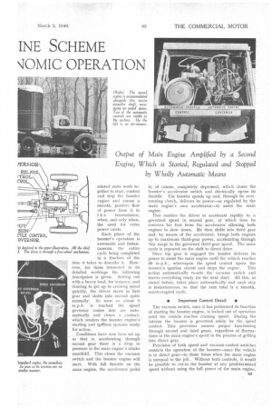
• Valuable Performance Gain • A booster-equipped vehicle may be expected to perform in high gear on hills 55-60 per cent. better than will a single-engined vehicle of the same gross weight. An articulated outfit with a gross weight of about 10i tons, for instance, will climb a 2 per cent, gradient in high gear at 25 m.p.h. An identical unit, boosterequipped, is reported to have climbed a 4 per cent, slope in high gear at 30 m.p.h.
With a single engine, an increase in gradient to 3 per cent, requires the use of third gear and the engine speed must be increased to 2,300 r.p.m. to maintain a road speed of 15 m.p.h. in that ratio. The booster-equipped unit, on the other hand, ascends the same slope in high gear at a road speed of 30 m.p.h. and an engine speed of only 1,850 r.p.m.
Assuming a 100-mile route with 15 per cent, of the distance in gradients of 3 per cent.—a total of 15 miles, in which the single-engined unit would have to proceed in reduced gear—the booster-equipped vehicle would gain 17 miles, or approximately 30 minutes, and this with about 100,000 fewer revolutions of the crankshaft of the main engine. Computing the driver's time at $1.00 an hour, and the availability of the unit for additional pay-loads increased by 30 minutes' time, saving $3.00 an hour, savings on the 100-mile trip, exclusive of fuel and maintenance, amount to $2.00. In a season's operation of 50,000 miles the savings at this rate would be $1,000.
Sponsors of the automatic booster put forward the following comprehensive claims : That it meets all advance requirements so completely as to usher in a new era in highway hauling, and that it affords a marked improvement in ton-miles per gallon, increased sustained speed between terminals with no rise in fuel consumption, high-gear operation on hills superior to that of lorries costing considerably more, decreased cost of driver's time because of greater speed, reduced use of gearbox, and generally easier driving, far less vehicle weight in comparison with pay-load capacity, time saved on daily runs, and greatly diminished maintenance cost.
.0 Straightforward Installation • The Clark automatic booster is designed for installation on the Chevrolet chassis without major change in the latter. The auxiliary engine is carried, an rubber mountings, by special brackets fastened to the frame side-members just behind the cab, its short propeller shaft running forwards, through a pair of universal joints, to the transmission.
The standard Chevrolet radiator core is replaced by a core of greater cooling capacity to handle the larger cooling job. Provision is made whereby the temperature of the cooling fluid in the booster engine corresponds with that in the main engine at all times, so that the full power of the former unit is always available under proper temperature conditions, no matter how long the periods between starts.
Apart from the economic benefits to be derived by the operator, is the improvement which general use of the device would presumably effect on highway traffic through elimination of the hazard created by heavily laden vehicles creeping up hills at 3-4 m.p.h. Recent agitation in America for some means for accomplishing this, either by legislating minimum speeds or by widening all hills, lends the announcement special interest in that country, and, without doubt, the position in Great 13ritain, so far as the danger and inconvenience are concerned, is not notably different.