


A Variable-ratio Steering Gear
Page 76
If you've noticed an error in this article please click here to report it so we can fix it.
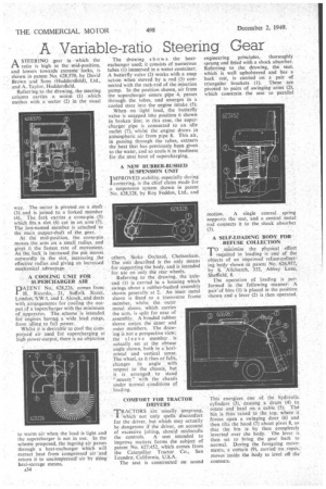
ASTEERING gear in which the ratio is high in the mid-position, and lowers towards extreme" locks, is shown in patent No. 628,370, by David Brown and Sons (Huddersfield), Ltd., and A. Taylor, Huddersfield.
Referring to the drawing, the steering column carries a worm (1) which meshes with a sector (2) in the usual way. The sector is pivoted „on a shaft (3)„ and is joined to a forked member (4). The fork carries a cross-pin (5) which fits a. slot. (6) cut in art arm (7). The last-named member is attached to the main output-shaft of the gear.
At Mid-position, the cross-pin moves, the .arm on a small radius, and gives it the fastest rate of movement. As the 'lock is, increased the phi moves outwardly in the slot, increasing the effective radius arid giving an increased
mechanical advantage,
A CODLING UNIT. FOR SUPERCHARGER AIR PATENT No.. 628,226, comps from H. Ricardo,.. 21; Suffolk Street, London,'S.W.I, and J. Alcoek, and deals with arrangements for cooling the output of a Supercharger with the minimum of apparatiis. The scheme'is intended for engines having a wide, load range, from idling to full power.
Whilst it is desirable to cool the cornpressed air used for supercharging at high power-Output, there is no objection to warm air when the load is light and the supercharger is not in use. In the scheme proposed, the ingoing air passes through a heat-exchanger which will extract heat from compressed air' and return itto uncompressed air by tising heat-storage means.
A34 • The drawing shows the heatexchanger used; it consists of numerous tubes (1) immersed in a water container. A butterfly valve (2) works with a snap action when moved by a rod (3) connected with the rack-rod of the injection pump. In the position shown, air from the supercharger enters pipe 4, passes through the tubes, and emerges in a cooled state into the engine -intake (5).
Whenon light load, the butterfly valve is snapped into position 6 shown in broken line; in this case, the supercharger pipe is connected to an idle outlet (7), whilst the engine draws in atmospheric air from pipe 8. This air, in passing through the tubes, extracts the heat that has previously been given to the water, and so cools it in readiness for the next bout of supercharging.
A NEW RUBBER-BUSHED SUSPENSION UNIT
I MPROVED stability, especially during cornering, is the chief claim made for ,a suspension system shown in patent No. 628,328, by Roy Fedden, Ltd.. and
others, Stoke Orchard, Cheltenham. The Unit described is the only means for supporting the body, and is intended for use on only the rear wheels. , Referring to the drawing, the 'axle. end (1) is carried in a housing which swings about a rubber-bushed assembly shown generally at 2. An inner metal • sleeve is fixed to a transverse frame • member, whilst the outer
metal sleeve, which carries the arm, is split for ease of assembly, A bonded rubber sleeve unites the inner and outer members. The drawing is not a perspective view; the sleeve member is actually set at the obtuse angle shown, both in a'horizo-ntal and vertical sense. The wheel. as it rises or falls, changes its angle with respect to the chassis, but it is arranged to stand " square" with the chassis under normal conditions of loading.
COMFORT FOR TRACTOR DRIVERS TRACTORS ale usuallyunsprung, 'which not only Spells discomfort for the driver, but which may actually be dangerous if the driver, on account of excessive jolting, should mishandle the controls. A seat intended to improve matters forms the subject of patent No. 627,452, which comes from the Caterpillar Tractor Co., San Leandro, California, U.S.A.
The seat is constructed on sound
engineering principles, thoroughly sprung and fitted with a shock absorber. Referring to the drawing, the teat, which is well upholstered and has a back rest, is carried on a pair of triangular brackets (1). These are pivoted to pairs of swinging arms (2), which constrain the seat to parallel
motion. A single central spring supports the seat, and a central metal rod connects it to the shock absorber (3) A SELF-LOADING BODY FOR REFUSE COLLECTION
TO minimize the physical effort required in loading is one of the objects of an improved refuse-collecting body shown in patent No. 626,957, by S. 'Allehurch, 332, Abbey Lane, Sheffield, 8.
The operation of loading is performed in the following manner: A pair-of bins (1) is placed in the position shown and a lever (2) is then operated.
This energizes one of the hydraulic cylinders (3), causing a drum '(4) to rotate and haul on a cable (5). The bin. is thus 'raised to the top, where it forces open a swinging door (6) and then tilts the hood (7) about pivot 8, so that the bin is by then completely inverted over the body. ' The lever is, then set to bring the gear back to normal. During the foregoing movements,' a curtain (9), carried, on ropes,' moves 'inside the body to level off the' contents.