


Patents Completed.
Page 38
If you've noticed an error in this article please click here to report it so we can fix it.
Piston-valve Two-stroke Motor. An Expansible Road Wheel.
A. L. COLMANT, No. 29,253, of 1912, dated ,inder International Convention, 20th December, 1911.—ii, this engine the lower end of the cylinder is closed and formed into a charging pump. The admission of the mixture to the primp is controlled by a valve situated at the side of the cyli inter.
The valve consists of a piston which moves across the inlet port from the carburetter, the travel being slightly more than twice the width of the port.
The piston is actuated by a crank, which is chain-driven from the engine-shaft; it is driven at the same speed as the engine. The valve crank is set 90 degrees behind the main crank.
The positioning of the two cranks at 90 degrees apart causes the valve to be wide open and travelling slowly during the time the pump-piston is moving most rapidly.
J. E. Smnrx, No. 10,426, dated 3rd May, 1913.—In this case a cast-steel or other metal wheel is formed with a solid hub having a number of radial spokes on it. The rim of the wheel has inwardly directed shanks, made integral with it, which are attached to the spokes.
One half of the rim is fixed definitely on the spokes, but the other half is built up of separate segments, each of which has a single shank fitted in a spoke. In the sectional part of the rim the shanks are adjustable, so that the rim can be expanded or contracted as desired.
The spokes on the hub are hollow, and the inner ends of the shanks on the rim are reduced in size to enter them; they are connected up by means of lock nuts. The various sections of the rim proper are bedded together On bevelled surfaces. -so that a tight fit is ensured.
The rim is contracted in size to allow of the tire being fitted ; it is then expanded to afford a proper grip.
V. AND E. TERRY, No. 28,987, dated 16th December, 1913. -In order to prevent waste of fuel in consequence of imperfectly-atomized liquid passing into the incInction pipe, the carburetter jet is made somewhat longer than usual and an additional spraying device is located above it.
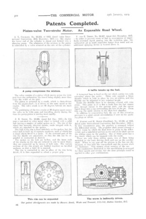
.A hexagonal base is fixed on the jet which carries two rods extending above the outlet. These rods support a brass thimble which is held in place by two set-screws, and the thimble can he adjusted to any required height. Inside the thimble there is an opening covered with wire gauze. This gauze is of so fine a mesh that the fuel cannot pass through except in the gaseous state, and the excess liquid drops into a cup surrounding the base of the jet. From this cup the spirit returns to the float-feed chamber. In addition to econctinizing fuel, the use of this invention prevents to a great extent accumulation of soot on the sparking plugs or valves.
P. FLEURY and H. Monti.; (Gauthier), No, 13,190, of 1913, dated under International Convention, 2nd December, 1912.— In this transmission gear, the gearbox is arranged behind the differential casing. The propeller shaft passes through a hollow worm by which the final drive is given to the differential, and a castellated portion on the end of the shaft carries the sliding gears in the gearbox. One of these gears has a dog-clutch, which can be engaged with the worm.
There are only three sliding gears, two of them being mounted on the main driving shaft and one on the countershaft. When in top gear all the pinions in the box are disengaged, so that both the countershaft and the reverse shaft are stationary. This ensures silent running of the car. The construction illustrated in this specification is arranged for three speeds and reverse, but the same principle could he applied to other gear combinations.