


A MAGIC CARPET
Page 16
Page 17
Page 18
Page 19
If you've noticed an error in this article please click here to report it so we can fix it.
of the road
THE performance of the Sunbeam trolleybus may well be likened to the smooth travel of the fabulous magic carpet. During acceleration from rest there is not the slightest snatch on the transmission, and the increase in speed, although rapid, is accomplished without discomfort to the passengers.
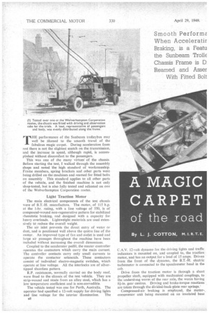
This was one of the many virtues of the chassis. Before starting the test, I walked through the assembly shops and noted the high standard of workmanship. Frame members, spring brackets and other parts were being drilled on the machines and reamed for fitted bolts on assembly This standard applies to all other parts of the vehicle, and the finished machine is not only shop-tested, but is also fully tested and adjusted on one of the Wolverhampton Corporation routes.
Light Traction Motor The main electrical components of the test chassis were of B.T.-H. manufacture. The motor, of 115 h.p. at the 1-hr. rating, with a line voltage of 550, is of compound-wound non-regenerative pattern for stabilized rheostatic braking, and designed with a capacity for heavy overloads. Lightweight materials are used extensively td reduce the overall weight.
The air inlet prevents the direct entry of water or dust, and is positioned well above the centre line of the motor. An improved type of fan and outlet is used and large air passages throughout the machine have been included without increasing the overall dimensions.
Coupled to the accelerator pedAl, the master controller operates the contactors which carry the main current. The controller contacts carry only small currents to operate the contactor solenoids. These contactors consist of individual electro-magnetic switches, which operate at line voltage. All the interlocks are of silvertipped shuntless pattern.
R.P. resistances, normally carried on the body roof, were fixed to the chassis of the test vehicle. They are strip-wound and niade from an alloy steel, which has a low temperature coefficient and is non-corrodible.
The vehicle tested was one for Perth, Australia. The operator had specified a 12-volt supply for driving lights and line voltage for the interior illumination. The HS
C.A.V. 12-volt dynamo for the driving lights and traffic indicators is mounted on, and coupled to, the traction motor, and has an output for a load of 15 amps. Driven from the front of the dynamo, the B.T.-H. electric tachometer is connected to the speedometer head in the cab.
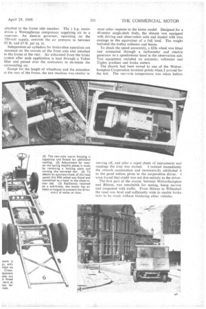
Drive from the traction motor is through a short propeller shaft, equipped with mechanical couplings, to the underslung worm of the rear axle, the worm having 8i-in. gear centres. Driving and brake-torque reactions are taken through the divided-back-plate rear springs: Compressed-air braking is employed, the motor-., compressor unit being mounted on an insulated base attached to the frame side member. The 1 h.p. motor drives a Westinghouse compressor supplying air to a reservoir. An electi ic governor, operating on the 550-volt supply, controls the air pressure to between 85 lb. and 65 lb. per sq. in.
Independent air cylinders for brake-shoe operation are mounted on the swivels of the front axle and attached to the frame at the rear. Air exhausted from the brake system after each application is lead through a Vokes filter and passed over the contactors to de-ionize the surrounding air.
Except for the length of wheelbase and the extension at the rear of the frame, the test machine was similar in most other respects to the home model Designed for a 40-seater single-deck body, the chassis was equipped with driving and observation cabs and loaded with iron castings to the equivalent of a full load. The weight included the trolley collector and boom.
To check the speed accurately, a fifth wheel was fitted and connected through a tachometer and electric generator to a speedometer head in the observation cab. Test equipment included an ammeter, voltmeter and Tapley gradient and brake meters.
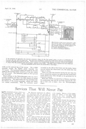
The chassis had been towed to one of the Wolverhampton Corporation terminal points when I arrived for the test. The rear-axle temperature was taken before moving off, and after a rapid check of instruments and readings the trial was started. I noticed immediately the smooth acceleration and momentarily attributed it to the good tuition given to the corporation driver. I. soon found that credit was not due entirely to the driver, The first part of the course. between Wolverhampton and Bilston, was unsuitable for testing, being narrow and congested with traffic. From Bilston to Willenhall the road was level and sufficiently wide to enable brake tests to be made without hindering other vehicles.
Day temperature was 59 degrees F. and the tarred road surface was soft, so that most of the brake tests were marred by wheel lock. Measured stopping distances from 20 4n.p.13 , employing the foot brake, proved that the Sunbeam could be brought to a halt in 20 ft Tapley readings taken during the test showed a maximum deceleration of 68 per cent., which is within the limits demanded by home operators lot passenger safety. Many opefators will not accept passenger vehicles which have a Tapley reading exceeding 70 per cent. when laden.
Hand Brake is Efficient The stopping distance of 57 ft. from 30 m.p.h. could have been improved with a more adhesive road surface. I was convinced that the brakes were well within the standard of the modern trolleybus. A check was made of the hand-brake efficiency from 20 m.p.h. Although the rear wheels locked, the stopping distance was 35 ft, on the first trial and 36 ft. on a repeat run.
At the end of the first series of brake tests there was insufficient level ground ahead for the checking of results. This was no problem for the corporation driver, who, moved the control lever to reverse and accelerated ". full astern" for 100 yds This was the first occasion on which I had travelled at more than 12 m.p.h. in reverse.
After turning at Willenhall, check brake tests were made and acceleration trials were started.Because of the lack of surge when moving away from rest, it was difficult to start the watch on the first movement. I found the answer by timing the test from the initial movement of the ammeter needle. Line pressure during these trials fluctuated between 500 and 550 volts, and this gave a slight discrepancy in the results.
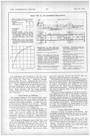
The Sunbeam has the typical electric-vehicle acceleration curve, rising steeply to 20 m.p.h. and flattening out between 25 and 30 m.p.h. The acceleration rate could be greater, according to the setting of the circuit breakers, but the maker has put passenger comfort before high performance: Limited acceleration wo ild also have an ultimate effect on the life of the transmission and body.
There are no serious gradients in the Wolverhampton area, especially on the route of the standard circuit, but with the permission of Mr. C. Owen Silvers, M.1.E.E., M.1nst.T., general manager of Wolverhampton Transport Department, the test was extended to the gradients between Wolverhampton and Sedgley. Balancing speeds were recorded on theinclines. On Morris Hill (1 in 20) 25 m.p.h. was maintained, on Spring Head (1 in 17i) 23 m.p.h, and on Gibbons Hill (1 in 20) the 25 m.p.h. speed of the first trial was verified.
Testing Rheostatic Braking Rheostatic braking was tested on the descent. The first notch reduced the speed from 20 m ph. to 14 m.p.h. on the 1-in-20 gradient. The second notch brought the vehicle almost to a halt.
Returning to the standard test route, I took the temperature of the rear-axle lubricant, finding it had risen from 66 degrees to 166 degrees F. in 11 hours' running. The outside casing of the traction motor was still cold, confirming that the power tests were being made below optimum conditions.
Final acceleration runs and balancing speeds were made on the outward leg of the course. On a slight downhill stretch, the highest speed recorded was 38.5 m.p.h. The maximum speed, governed by the safe speed of the traction-motor armature, of the test vehicle was 43.2 m.p.h. The balancing speed on level ground was 34 m.p.h.
Road surfaces in the Wolverhampton area are above average condition and there was little chance of testing the suspension. The observation cab was furnished like the interior of the normal passenger vehicle and riding was indeed comfortable. With the contactor panel mounted on the side of the frame and the trolley boom secured behind the observation cab, the entire test was made in silence.
There was only one occasion during the test when the driver missed the contacts, but otherwise the acceleration could almost have been thought to be governed by an automatic control.
When the vehicles are operating in Western Australia, the acceleration rate will be increased, because the voltage in that area is higher than the Wolverhampton supply.