A System for Correcting Brakes
Page 50

If you've noticed an error in this article please click here to report it so we can fix it.
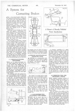
ON a four-wheel-braked vehicle the optimum braking force is a function of the wheel loads, and although efforts have been made to allow for this, by increasing the brake action on the front wheels, for example, the result is only approximately correct. A scheme claimed to provide correct brake force under all conditions of load is shown in patent No. 5r.v0,755, by S. A. Andre Citroen, Paris.
Referring to the drawing, the brake pedal acts against a thrust-plate (1), which divides the force between the two master cylinders (2). These operate the separate frontand rear-brake systems, as clearly indicated by the piping. lithe pedal acts in the middle of the thrustplate, the forces are evenly divided between front and rear.
The rear axle is fitted with a rocking fork (3), which changes its angle with a change in load. The setting affects a master cylinder (4), which governs, in turn, the position of a slave cylinder (5); this controls the height of the pedal thrust line. Therefore, if the rear axle be heavily, loaded, the pedal is brought nearer to one of the master cylinders and recedes from the other, so that the force ratio is automatically. varied. According to the drawing, increased load on the rear axle weakens its braking effort; whether this be intentional, or an error in drawing, we are uncertain.
A UNIFLOW-SCAVENGED TWO-STROKE
THE use of uniflow-scavenged twostroke engines has not, so far as we are aware, been applied to road vehicles, hut it may conceivably be possible in the future, and an engine of this type is shown in patent No. 589,988, by A. B. Atlas Diesel, Stockholm, Sweden. The design is said to be particularly suitable for small highspeed engines.
The drawing shows the general layout of the cylinders, each of which has two opposed pistons and a crankshaft at each end. At outstroke dead centre (as shown) an air-blast is directed into the inlet ports (1) while the exhaust leaves via lower ports (2). This is the " uniflow " system and has the advantage of giving a complete straightthrough scavenge on every outstroke. The basis of the patent is the design of the cylinder ports (3); these are given a sharp 90-degree turn along the cylinder so as to eliminate any tendency to spin the air as it travels down the cylinder.
AUTOMATIC MAINTENANCE OF ENGINE-OIL LEVEL
A SCHEME for automatically main
taining the correct level of engine oil is shown in patent No. 591,056, by M. Barton, "The Hollies," Bilborough Road, Wollaton, Notts.
The vehicle is provided with an additional tank (1) to accommodate a quantity of oil. Built on to the tank is a piston-pump (2), which forces the oil through a pipe (3) into the engine sump. A second pipe (4) acts as an overflow, returning oil to the tank when the correct level is reached.
The pump unit is worked every time the foot brake is applied, either by direct mechanical coupling or by the suction applied to a servo motor, as shown. In this case a pipe (5) is used to connect the pump with the servo cylinder (6).
A LOAD-DISTRIBUTING ATTACHMENT FOR LORRIES _
THERE will be many uses for a
scheme disclosed in patent No. 591,144, which shows a device for uniformly discharging the load at a steady rate as the vehicle moves forward. The patentee is E. Green, Valley Works, Kensworth, Dunstable, Beds. A conveyer, consisting of a chain carrying spaced slats along the floor of the body, passes outwards under an adjustable gate (1). After leaving the gate, it passes through a short mid-air section (2) and then curves around pairs of sprockets supported by a framework
(3). The framework completely surrounds the body, so that the conveyer moves in a closed circuit. It is driven through a chain (4) and by a sprocket on the back aide (5). The unit (6) is an adjuster for setting the tension of the main chains.
As the vehicle proceeds, the slats are filled with material, the rate of discharge being controlled by the height of the adjustable gate. The load falls on to the ground as it passes over the unsupported portion at the rear of thg gate.
AN IMPROVED TOOL FOR MEASURING ANGLES THE standard workshop method of accurately setting up an angle is to use a sine-bar, one end of which is packed up with slip-gauges This is a troublesome process and the bar, when set, cannot be moved without the risk of tumbling over the pile of slips. A tool which overcomes these objections is covered by patent No. 590,862, from S. Worby, 66, Margaret Road," New Barnet, Herts.
The tool follows the outline of the ordinary sine-bar, but it is provided at one end with a pivoted micrometer head (1) of sturdy construction. This can be set to any desired height, and takes the place of slip gauges. The micrometer calibrations include a vernier capable of giving an angular setting correct to one minute of arc. For settings beyond the range of the micrometer, a range of extension blocks is used; these can be screwed into a hole in the base.


