


NEW PRODUCER-GAS PLAN
Page 20
Page 21
If you've noticed an error in this article please click here to report it so we can fix it.
OF PROGRESSIVE DESIGN ALTHOUGH the majority of makes of vehicle producer-gas plant on the British market operate on the cross-draught principle, the up-draught type has certain pronounced and unquestionable advantages. More than ordinary interest, therefore, attaches to an apparatus that has recently made its appearance and which functions purely as an up-draught unit.
This, however, is not the only feature of note it possesses. There are several other points in the specification of the plant which are definitely of a• progressive nature and which 'represent determined efforts, on the . part of those responsible, to get over difficulties that are tending to militate against the popularity of solid fuel used in this manner.
Maker a Gas Engineer W. and B. Cowan, incorporated in Parkinson and Cowan (Gas, Meters), Ltd., Terminal House, 52, Grosvenor Gardens, London, S.W.1, and 2, Fanlan Street, S.E.11, is the maker, and the company's gas experience is unmistakably reflected in the product.
Among the specially notable points referred to may be named the method of introducing water to the fire, the design of the grate and the means for ;eading off the gas from the producer, the provision of a valve on the outlet pipe for permitting a slo* draught when the plant is standing, the filtering and cooling arrangements and the petrol-gas change-over control.
Before dealing with these fully and describing the general lay-out, it should be mentioned that three types of producer are available. The smallest has hopper and hrebox of the same diameter (1 ft. ,1 in. external). The intermediate model (as illustrated) has a larger hopper measuring 1 ft. 6 ins, in diameter.
Both are about 4 ft. in height. The largest is roughly 7 ft. high and, like the smallest, has a constant outside diameter of 1 ft. 1 in. It is designed for installation in a narrow• compartment immediately behind the driver's seat and is suitable for vehicles of the maximum-load 30m.p.h. class.
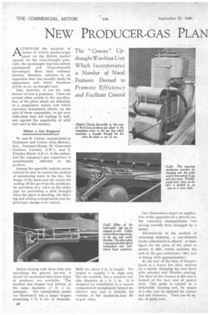
Our illustrations depict an application of the apparatus to a private car, the concern's demonstration van having recently been damaged by a bomb.
Alternatively to the method of .mounting depicted,. a one-wheeled trailer attachment is offered. A basic figure for the price of the plant as shown is £85, which excludes the cost of the gas carburetter (R5) and of fitting (.C15 approximately).
M the rear of the base of tha.producer is .a heavy fire door, secured by a sturdy clamping bar and faced with asbestos and Headite jointing. The floor of the furnace is flat and is formed of fire bars cast of special steel. This grate is carried in a detachable housing and, by means of a bar, can be agitated for clinker and ash clearance. There are 62 sq. ins, of grate area.
Fcrruling the walls of the furnace is a thick refractory lining (9 ins. internal diameter) and just entering the top of this is a special gas offtake—a deep annulus of inverted U section, from a point in the top of which the gas outlet pipe leads off.
This pipe then assumes a larger diameter, incorporates an elbow, runs vertically downwards to another elbow and enters the first-stage filter. Running axially through the vertical section of the pipe is the tube which admits to the fumace primary air and water, the latter being. vapourized during its passage there-along.
Water-feed Arrangements At-the intake end of this tube there are two orifices—one in line, the other on a branch, joining the main pipe at an angle. In each there is a sleeve functioning more or less as a venturi, and adjustable in respect of position. Sight glasses are incorporated in the branches. Ending inside each venturi is a small-bore waterfeed pipe. These draw their supply from a small tank, the level of which is regulated by a float chamber. The object of the double orifice is to maintain a better degree of constancy of water-air proportion with varying air speeds. Water is supplied to the float Chamber from a tank mounted high on the side of the producer.
Between the venturis and the hot jacket, a simple shut-off air valve .is fitted to the primary-air pipe. This is Opened for starting up the fire When a dry blast is required. Methy lated spirit, on an asbestos pad, is recommended for lighting up. The operation takes about 4 mins.
Goilig back now to the gas line, we find in the first part of the system three cleaning and cooling units, coarse and fine baffle boxes and an annular chamber with tangential inlet and outlet pipes. The last-named affords a big cooling area, and is provided with an enlarged part at the base for the accumulation of dust, etc., and for facilitating cleaning. These are clearly seen, in accompanying illustrations; on the off side of the producer.
On the near side is the filter proper, or purifier. In it are three trays carrying a 4-in, layer of coke, a pa,d of compressed sisal and a wad of wire wool. Thence the gas is conveyed to the mixing valve. All joints and Covers appear to be well made and Ofadeiluate strength. Incorporated in the pipe between the cleaners and the purifier is an atmospheric valve which is opened when the engine is stopped and allows gas to escape and air to enter the fire to keep it burning slowly for the next start up. We are informed that 12 hrs. is quite a reasonable period for standing and restarting without rekindling.
No alteration has been made to the existing induction arrangements beyond the new gas connections. Two carburetters are used on the S.S. car we inspected and the connections are fitted between these and the induction ports. There is a throttle valve in the gas pipe and on the producer side of this a branch pipe comes in from the hand-controlled plungertype air valve. Air enters this via a long flexible pipe ending below the car and well to the rear.
On the producer side of the branch there is another lead-off to a vacuum gauge on the dashboard.
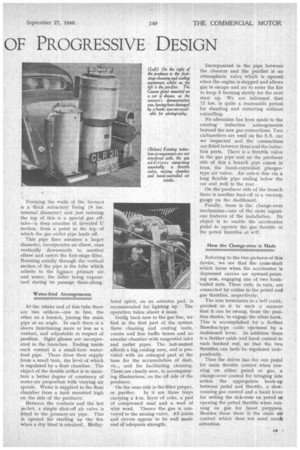
Finally, there is the change-over mechanism—one of the most ingenious features of the installation. Its object is to enable the accelerator pedal to operate the gas throttle or the petrol throttles at will.
How the Change-over is Made
Referring to the two pictures of this device, we see that the cross-shaft which turns when the accelerator is depressed carries an upward-pointing arm, engaging one of two hook'ended rods. These rods, in turn, are connected by cables to the petrol and gas throttles, respectively.
The arm terminates in a bell crank, pivoted to it in such a manner that it can be swung, from the position shown, to engage the other hook. This is accomplished by a further Bowden-type cable operated by a dashboard lever. In addition there is a farther cable and hand control to each hooked rod, so that the two throttleS can both be regulated independently.
Thus the driver has the one pedal for main throttle control when running on either petrol or gas, a change-over control for bringing into action the appropriate hook-up between pedal and throttle, a slowrunning gas control and a hand lever for setting the tick-over on. petrol or opening the petrol throttle when running on gas for boost purppses. Besides these there is the main air control which does not need much attention.