


• FORD VAN POINTERS.
Page 19
Page 20
If you've noticed an error in this article please click here to report it so we can fix it.
By R. T. Nicholson (Author of "The Book of the Ford ").
N THIS NUMBER I am going to deal with two or three little odd jobs that sooner or later want doing about every Ford—jobs which any handy man can do for,himself, if he. has time, though they are generally put out, because he has not—or thinks he has not.
80. —Replacing the Commutator Brush.
It is wonderful how long the commutator brush will work without giving trouble. I .could preach a sermon on the stick-to-it-ive-ness of the commutator brush. It is going, going, going, all the time—round and round and round—never getting sick of the mono-, tony of its job, never asking for more money, just. keeping hard at it all the time.
But it does think of going on strike at last—though only when it is pretty nearly worn out. Then it sets thEs engine firing jerkily—possibly missing at times. It has a Iffe of at least 5,000 miles in the ordinary way—possibly half as much again if you regularly and liberally oil your commutator. Neglect of lubrication can break it down in as many hundred miles.
Even if you do not notice anything amiss with the firing of your engine, it is not a bad plan to replace the brush every 5,000 miles or so, for your engine has not a really good chance with a worn brush. Generally, you will be pleasantly surprised by the improved running of your engine when you replace an old brush with a new one.
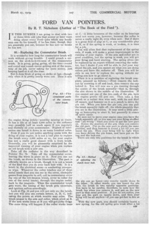
Take ofr the radiator in the way described in Pointer No. 79. Take off the commutator cover, leaving the wires in place on it. Now you can see the brush, as shown in the illustration. The part is officially known as a brush, though it is not a brush. of the kind that you do your back hair with. It is a brush in the electrical sense—a, conducting sweeper, or wipe. Whenever the roller touches one of those metal insets that you can see in the cover, electricity passes from magneto to coil, coil to commutator cover (by one of the low-tension wires), cover to roller (by one of the metal insets), through the engine metal, back to the magneto. When the commutator brush gets worn, the timing of the brush gets uncertain, and ignition suffers accordingly. Look at Fig. 02 and you will not only see the brush, but you will also see certain letters, A, B, C, indicating the points at which trouble may arise. The brush proper is the arm and roller, which pivot at B. If the arm works loose at B you vrill-get,jerky firing. The same thing will happen if the roller works loose at C. = A little looseness of the roller on its bearings need not worry you, however, because the roller is never a really tight fit, even when new. But if there is a great deal of pla,y at C, or any considerable play at B, or if the spring is weak, or broken, it is time for a job. You will often find that replacement of the spring only, if weak, will make a great improvement in the running of your engine. If the arm and roller are in good condition, but the spring is weak, you will get poor firing and hard starting. The spring alone can be replaced by an expert without removing the radiator, but I doubt if you will be able to feel your way about the job, and you cannot see what you are doing unless you have the _radiator off. Then you will be able to see how to replace the spring withoilt my telling you how to go about it.
. When it is a question of replacing the brush complete, proceed as follows : —First remove the locknut by screwing it off and back, then remove the cap behind it. You will new see a pin running through the centre of the brush assembly—that is, through the slot shown in the middle of the illustration. If you cannot see one of the two ends of the pin, turn the engine gently till you can. Then take a fine punch or a rather thin wire nail, with its end filed off square, and hammer on it as a punch to drive the pin out. When you have the pin out, you can pull the brush assembly right off—the whole assembly that you see in the illustration. It may need a little prizing or humouring to start it, but generally it comes off quite easily.
Be sure not to move your engine once you have the brush assembly off, or you may get your firing shuffled and "all wrong ". when you come to put the new part on. Notice the position of the arm when you remove the old part. Put on the new part in about the same position; and then humour it round a bit till you can insert the pin. Then your firing will be right when you have driven the pin home, and have put on the cap and the lock-nut.
There are only two positions for the brush in which the pin can go home—one exactly upside down to the other. In other words, you can insert the pin with the brush in two exactly opposite positions. . You have to be careful, therefore, to note how the brush lies when you remove it, and put on the new part in that same position. If you do not, notice, you may get the part on upside down, and then your firing will be. all anyhow—if you can get her to fire at all.
With the new part, you should certainly insert a new spring, for the old spring gets weak after a lot. 049
of use, and you will only get satisfactory firing—and particularly satisfactory starting—if the spring pulls "hith good tension.
8I.—Adjustment of Clutch Lever Bolt.
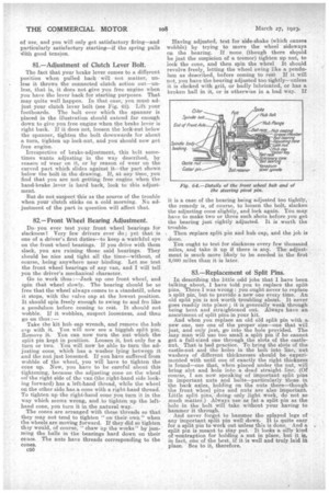
The fact that your brake lever comes to a different position when pulled back will not matter, unless it throws the connected clutch action out—unless, that is, it does not give you free engine when you have the lever back for starting purposes. That may quite well happen. In that case, you must ad-. just your clutch lever bolt (see Fig. 63). Lift your footboards. The bolt over which the spanner is placed in the illustration should extend far enough down to give you free engine when the brake lever is right back. If it does not, loosen the lock-nut below the spanner, tighten the bolt downwards for about a turn, tighten up lock-nut, and you should now get free engine.
IrreSpective of brake-adjustment, this bolt sometimes wants adjusting in the way described, by reason of wear on it, or by reason of wear on the curved part which slides against it—the part shown below the bolt in the drawing. If, at any time, you find that you are not getting free engine when the hand-brake lever is hard back, look to this adjustment.
But do not suspect this as the source of the trouble when your clutch sticks on a cold morning. No adjustment of the part in question will affect that.
82.—Front Wheel Bearing Adjustment.
Do: you ever test your front -wheel bearings for slackness1 Very few drivers ever do ; yet that is one of a driver's first duties—to keep a. watchful eye on the front wheel bearings. If you drive -with them slack, you are ruining those said bearings. They should be nice and tight all the time—without, of course, being anywhere near binding. Let me test the front wheel bearing& of any van, and I will tell you the -driver's mechanical character.
Go to .work thus :—Jack up one front wheel, and spin that wheel slowly. The bearing should be so free that the wheel always comes to a standstill, when it stops, with the valve cap at the lowest position. It should spin freely enough to swing to and fro like a pendulum before coming to rest. It should not wobble. If it wolables, suspect looseness, and then go on thus :— Take the kit hub cap wrench, and remove the hub cap with it. You will now see a biggish split pin. Remove it. You can now turn the nut which the split pin kept in position. Loosen it, but only for a turn or two. You will now be able to turn the adjusting cone, which has a washer lying between it and the nut just loosened. If you ha,v.e suffered from wobble of the. wheel, you will have to tighten the cone up. Now, you have to be careful about this tightening, because the adjusting cone on the wheel on' the right side of the van (the right-hand side looking forward) has a left-hand thread, while the wheel on the other side. has a. cone with a right-hand thread. To tighten up the right-hand cone you turn it in the way which seems wrong, and -to tighten up the lefthand cone, you turn it in the natural way.
The cones are arranged with these threads so that they may not tend to tighten " on their own" when the wheels are moving forward. If they did so tighten thy would, of Course, " ohaw up the works" by jamming the balls in the bearings hard down. on their cones. The huts have threads corresponding to the cones.
c50 Having adjusted, test for side-shake (which causes wobble) by trying to move the wheel sideways on the bearing. If none (though there should be just the suspicion of a tremor) tighten up nut, to lock the cone, and then spin the wheel It should revolve freely, letting the wheel swing like a pendulum as described, before coming to rest If it will not, you have the bearing adjusted too tightly—unless it is choked with grit, or badly lubricated, or has a broken ball in it, or is otherwise in a bad way. If
it is a case of the bearing being adjusted too tightly, the remedy is of course, to loosen the bolt, slacken the adjusting cone slightly, and lock again. You may have to make two or three such shots before you get the bearing just rightly adjusted. It is worth the trouble.
Then replace split pin and hub cap, and the job is done.
You ought to test for slackness every few thousand miles, and take it up if there is any. The adjustment is much more likely to be needed in the first 2,000 miles than it is later.
83.—Replacement of Split Pins.
In describing the little odd jobs ,that I have been talkingabout, I have told you to replace the split pins. There I was wrong: you ought never to replace a split pin, but to provide a new one every time. An. old split pin is not worth troubling about. It never goes readily into piaee ; it is generally weak through being bent and straightened out. Always have an assortment of split pins in your kit.
And when you replace an old old split pin with a. new one, use one of the proper size—one that will just, and only just, go into the hole provided. The lazy man will use too small a split pin if he cannot get a full-sized one through the slots of the castlenut. That is bad practice. To bring the slots of the castle-nut and the holes in the bolt into line, nut washers of different thicknesses should be experimented with until one of exactly the right thickness is found—one that, when placed under the nut, will bring Blot and hole into a dead straight line. (Of course, I am now speaking of important split pins in important nuts and bolts—particularly those in the back axles, holding on the nuts there—though the front wheel pins and nuts. are also important. Little split pins, doing only light work, do not so much matter.) Always use as fat a split pin as the hole in the bolt will take without your having to hammer it through.
And never forget to hammer the splayed legs of any important split pin well down. It is quite easy for a split pin to work out unless this is done. And a split pin is meant to stay put. It looks a silly kind of .scontraption for holding a nut in place, but it in fact, one of the best, if it is well and truly laid in plate. See to it, therefore.