


Preventing Whip in Gearbox Shafts
Page 36
If you've noticed an error in this article please click here to report it so we can fix it.
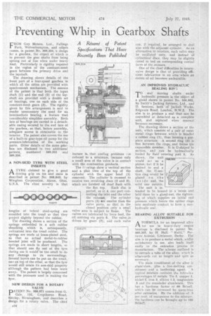
A Risme. of Patent Specifications That Have Recently Been Published rRom Guy Motors, Ltd., Fallings 1 Park, Wolverhampton, and others Comes, in patent No. 569,354, n, design for a gearbox, the object of which is to prevent the gear shafts from being sprung out of line when under heavy load. Particularly is rigidity required in the region of the constant-mesh gears between the primary drive and the layshaft.
The drawing shows details of the font part of a four-speed gearbox in which all the ratios are provided with synchromesh mechanism. The essence of the patent is that both the input shaft (1) and the end (2) of the layshaft are provided with a double set of bearings, one on each side of the constant-mesh gears (3). The rigidity given by this arrangement is said to render unnecessary the need for an intermediate bearing, a feature that considerably simplifies assembly. Both iets of bearings are carried in a_detachable casing secured to the end lace of the gearbox, so that, before assembly, adequate access is obtainable to the interior. The patent also covers the use of a built-in gear-type oil pump for the pressure-lubrication of the working parts. Other details of the same gearbox are disclosed in two additional patents, numbered 369,355 and 569,356.
A NON-SKID TYRE WITH STEEL INSERTS ATYRE claimed to give a good driving gtip on ice and snow is described in patent No. 568,843, by Wingfoot Corporation, Akron, Ohio, U.S.A. The chief novelty is that
lengths of helical steel-spring are moulded into the tread so that they project slightly beyond the rubber.
The drawing shows a section of the springs embedded in a soft rubber sheathing which is, sub§equently, vulcanized into the tread rubber. The springs are made of brass-plated steel, so that an actual metal-to-rubber bonded joint will be produced. The springs are made in short lengths, so that should one fly out of the tyre during use it svould-be too small to do any damage to its surroundings. Several layers can be put on the tread, one on top of the other, so that the tyre' would still retain its non-skid property although the pattern had been worn away. The patent is largely concerned with, the processes used in malting. the Lyre.
NEW DESIGN FOR A ROTARY VALVE
PATENT No. 568,971 comes.from G. Gale, 132, Cropthorne Road, Shirley, Birmingham, and describes a design for a rotary valve. The thief
feature is.. that cooling problems rre reduced to a minimum, because only a small area of the valve is in contact with the combustion products.
The di-lwings show a vertical section anti a plan view of the' top of the cylinder with the upper head ( I ) removed. The cylinder is recessed to receive two revolving discs (2 and 3), which are finished off dead flush with
the flat top. Each disc is ported, as at 4, one port controlling the inlet and the other the exhaust The cylinder ports (5) are smaller than the valve ports, so that in the closed position only a small
valve area is subject to. flame. The valves are lubricated by force feed, the oil arriving via ports 6. The valveais driven by gears (7 ) ; arid each valve
can, ff required, he arranged to deal also with the adjacent cylinder. As an alternative to rotation, each valve may be oscillated only, and instead of cylindrical discs, they may be sligbtly coned to bed on corresponding coniCal faces of the recesses.
One of the chief difficulties in rotary. valve design is that of providing efficient" lubrication in an area where an excess of oil becomes undesirable.
AN IMPROVED HYDRAULIC SEALING REN
rseal moving shafts under hydraulic pressure is the Object of a gland shown in patent No. 568,902, by Smith's Jacking Systems, Ltd., and D. Sessions, both of jackal) Works, Edgware Road, London, N.W.2. The aim is to produce a seal that can be assembled or detached as a complete unit, and replaced when renewal becomes necessary.
The drawing shows a section of the unit,, which consists of a pair of outei metal rings between which is bonded a rubber ring •(1), thus forming a onepiece structure. A second ring (2) is free between the rings," and forms the expansible member. It is U-shaped in section, and can be hydraulically loaded by fluid' entering port 3, As showit the unit would act as a piston,: hut, if it be desired to seal a shaft, the Id-section ring Would be placed on the ins id e, and, the solid one outside,
The unit is intended to he housed in a receSs am held there by a gland-nut, the tightenins; of which supplies' an initial end pressure which forces the rubber rings into moderate coatact to form a nonhydraulic seal.
BEARING ALLOY SUITABLE FOR E XTRUSION
AFORMULA for an improved alloy for use in heavy-duty engine bearings is disclosed in patent No. 569,337, by H. Hall, " Kulti," PasturesAvenue, LittIeover,•Derby. The aim is to produce a' metalwhich, whr.st satisfactory in use, also lends itself easily to the extrusion process in manufacture. The scheme outlined is to extrude a tube of the alloy, which is altarwards cut to length and split as
n ecessary • • •
The main Constituent of the' alloy is aluminiam, plus a low-melting constituent and ,a hardening agent. f A typical mixture contains the following percentages bf metals: Tin 5, copper 4, nickel 2, iron 3, silicon 1.2, magnesiurn .5 and the remainder aluminium. This has a hardness factor of 60 Brinell, which can be increased by quenching after extrusion. By the addition of per ceut, of manszanese to the mixture, the hardness can be brought up to 1100 Brinell,'