


Patents Completed.
Page 20
If you've noticed an error in this article please click here to report it so we can fix it.
Complete specifications of the following patents will be sent to any address in the United Kingdom upon receipt of eightpence per copy at the Sale Branch, Patent Office, Holborn, W.C.
SPOUTS FOR PETROL CANS.—ti. W. Cox.—No. 15,172, dated 23rd June, 1910.—The invention described in this specification consists of art improved form of spout attachment for use in connection with petrol containers and similar vessels. The arrangement is specially applicable to that kind of petrol can which is provided with a vent tube, the mouth of which pre. jects from the inside into the mouth of the can, for admitting air while the contents are being poured. The usual arrangement is open to the objection that the vent mouth is liable to be obstructed by the outpouring liquid, and if the ordinary tube or spout be affixed to the
mouth of the eau, further obstruction as a rule results. The patentee arranges for the holding of two tubes suitably disposed in a conveniently-formed screw cap. The larger spout, which is curved towards its upper end. communicates direct with the interior of the petrol can. The smaller and shorter tube is so arranged that it fits into the upper end of the vent, which is normally a part of the petrol can. It will therefore be seen that the petrol outlet and the vent pipe are independent. Alternative methods of fixing a device of this kind to the outlet of a petrol can are suggested. One of these methods is the mounting of the two tubes in a suitable resilient body, e.g., cork, which can be forced firmly into the can mouth.
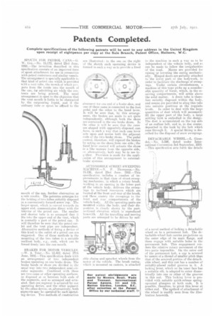
BRAKES FOR MOTOR VEHICLES. --W. A. Trier.—No. 15.412. dated 27th June, 1910.—This specification deals with an arrangement of two independent. brakes operating on one brake drum. The brake bands or shoes are divided in the usual way into two independent semi-circular segments. Combined with these are two cams or other operating surfaces. so disposed at or between both ends of the segments, and so arranged and actuated, that one segment is actuated by one operating device, and the other segment by the other device, or, alternatively, both segments may be operated by each operating device. Two methods of construction are illustrated in the one on the right of the sketch each operating device is formed in such a way as to provide a fixed
abutment for one end of a brake shoe, and one of these cams is connected to the foot pedal and the other to the hand lever, It will he seen that, by this arrangement., the brakes are made to act quite independently, although both the shoes are contained in the one brake drum. In the other it will be seen that the cams are shaped with oppositely-disposed cam faces, in such a way that each cam lever acts upon and moves both the adjacent ends of the two brake shoes. The pedal control. therefore, will expand the brakes by acting on the shoes from one side; the hand lever control will actuate the shoes in a like manner from the opposite side,
alternatively. both may he in use to then Provision is made for the application of this arrangement to externalbrake systems.
AUTOMOBILE STREET-SWEEPING INIACIIINE.—N. P. Thompson.—No. 15.156, dated 23rd June, 1910.—This specification includes a number of improvements in that class of street-aweeping mechanism, in which a rotary brush, working in an opening in the lower part of the vehicle body, delivers the sweepings to inclined conveyors which are located at the front and rear of the brush, and these eonvey the sweepings to the front and rear compartments of the vehicle body. All the operating parts are mounted within the body. and their dieposition is clearly shown by the partseetional elevation which is reproduced herewith. All the travelling and moving parts are arranged to be driven by suit
able chains and sprocket wheels from the motor of the vehicle. The brush casing, which is mounted on castors, is attached
to the machine iii such a way as to be independent of the vehicle body, and so can be made to follow the irregularities of the road. Means are provided for raising or lowering the casing mechanically. Hinged doors are suitably attached to the lower part of the bodywork, in order to facilitate the discharge of sweepings. Under certain circumstances, a machine of this type picks up a considerable quantity of water, which, in the receiving compartments, will settle above the solid matter. A drain tube is therefore suitably disposed within the body, and means are provided to sling this tube into suitable positions at the requisite levels. In order to deal with the large quantities of dust. which will necessarily fill the upper part of the body, a large settling tank is embodied in the design. The dust is accumulated on the top side of an endless belt, and is, in due course, deposited in the tank by the belt which runs through it. A special fitting is described for the disposal of snow sweepings.
DETACHABLE WHEEL.—L. Girardot.—No. 5,590, dated under International Convention 3rd September, 1910. —This specification sets forth the details
of a novel method of locking a detachable wheel on to a permanent hub. The detachable-wheel hub carries projections on the outer edge of its main flange, and these engage with suitable holes in the permanent hub. This engagement renders the relative rotary movement of the two parts impossible. On the outer end of the permanent hub, a cap is screwed by means of a thread of smaller pitch than that of the screwed portion of the-detachable wheel, and this nut has a number of suitably-placed radial grooves in it. A locking lever, which on its inner face has a suitable rib, is adapted to enter diametrically into one or other of the grooves in this nut. This locking lever is provided with suitable quick-release springoperated plungers at both ends. It is possible, therefore, to pivot this lever at either end. The nethod of attachment of the wheel is readily seen from the illustration herewith.