


A Single-plunger Injection Pump
Page 60
If you've noticed an error in this article please click here to report it so we can fix it.
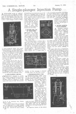
.A .SIMPLIFIED• design • of inje'etion .1-1. pump comes in patent No. 631,005; from the. I nteroational Harvester 'Company of Great Britain, Ltd,-,,259., City. Road,.London,E.C.1.The chief feature is that a single plunger is used to supply
a multi-cylindered engine, the output being. directed by a' rotary distributor; '
In the drawing, 'the main'Shaft Carries' a cam (I) provided with as thany lobes as there are cylinders to the engine; The cam -wrirk's the • plunger' in the' usual way, and the' output is -EilS.0 con-: trolled in the ConVentional manner. rotating the helically edged plunger via a pinion (2). • • The -novelty. lies in the use 'of a rotary cylinder barrel (3) in which the plunger works. Jr is provided With helical gear-teeth (4), which are driven by -a vertical shaft_ (not shown) from a helical gear. (5) on the camshaft.' As the barrel revOlves, a radial.diseharge-port registers successively with delivery passages in the body, and these lead' to' -individual outlets (6), in which arc located the 'one-way discharge valves.
. A .LOG-LOADING DEVICE ORIG1N ALLY designed to enable a timber transporter' to load its own logs, a scheme :shown' in patent No. 631,490, _could, be adoptedto handle many other types of load.. The patentee
is R. G. Le Tourneau, Inc., Peoria, Illinois, U.S.A.
The vehicle is fitted with an overhead . rail (1) supported on a single upright at the front and an arched member (2) at the rear. On the rail runs a trolley A34
(3) :whicii-cari be hauled one way or the, other by &complete loop of cable l4) wound on a.power-driven drum (5). The hook can • be raised or, lowered by -a second.' Cable fixed at point 6, looped under. pulleys (7) on the —
trolley,. and hauled'. by a • second winch (8). By the use of this arrangement • of cables,the lifting
action is • quite independent of the lengthwise location of the trolley.
A FILTER FOR USE IN INJECTORS..
D ATE/NT No. 630,272
• I shows a final filter which' is small and cam pact enough to be housed in the body of an injee tor. The patentee is G. .• Sola, Turin, Italy.
The drawing shows a section and a plan view of the filter; it is•of washer like form and can be easilY accommo
dated and clamped in the assembly. of -the injector. It consists of two parts. an outer ring (1) and aninner plug (2) pressed together. The-plug is of onlygonal outline, it's shoWn at 3, so 'that,
• when forced into a round hole,' a , number of fine passages is formed through which the fuel has to pass.
A REFRIGERATING UNIT
A REFRIGERATING UNIT which 1Th can be readily fitted to a foodcarrying vehicle is shown in :patent Ni,. 631,037, by the U.S. Thermo Control Co., Minneapolis, U.S.A. The unit is reasonably compact. and being self-contained, needs no external pipework or other connections.
The drawing shows an outline of the apparatus if( place on the vehicle body. It is mounted high op at the front of the body (I), which is doublewalled for the Purpose of heat insulation. The freezing section (2) is housed inside the body, whilst the compressor and its petrol engine (3) are carried outside, where they can be adequately cooled by air flowing through the radiator (4).
An important feature of the scheme is the circulatinrsystern for the cooled air; this is blown into a central trunk along the top of the body and emerges from .both sides, so that the walls are • kept 'cool by a constantly descending stream of cold air.. The warmed air is collected from a central point_ 'on the floor and led back to the cooler. .
A DUTCH SLEEVEVALVE ENGINE
ASLEEVE -VALVE engine from Holland forms the subject of
patent No. • 626,770, which comes from M. Kleine, 'Amsterdam.
Two sleeves are used, a lower one (1) controlling the exhaust holt .(2) and a shorter upper one (3) which .controls an inlet space (4). The lower sleeve is moved by a grooved cam (5) via a bell-crank (6), but a
• feature of the.patent is that most, of the sleeve movement is caused by piston friction, the cam merely, defining its limits, The upper inlet sleeve is biased into the open position. by springs (7), but is mostly kept closed' by abutting on the end of the exhaust sleeve. The-cycle is as follows-. froth top dead-centre-the exhaust 'sleeve descends a short. distance, and . the inlet sleeve follows,
opening, its ports. .
On the compression stroke, the lower sleeve ascends, closing both seat ings, and they remain so until neat the bottom of the powerstroke. At this point it becomes-necessary for the inlet valve to remain seated, while the exhaust sleeve moves away.
This is done by gas pressure, which enters small ports (8) and applies upward force to a number of srnall pistons (9), which can then overcome the opening force of the inlet-sleeve springs, and thus the sleeve is kept on its seating..