


Modern Technique in Gear Production
Page 44
Page 45
Page 47
If you've noticed an error in this article please click here to report it so we can fix it.
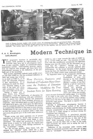
THE progressive increases in permissible gear stresses, made possible by improvements in the materials used, have led to advantageous reductions in gear assembly weights of commercial-vehicle transmission systems. Unfortunately, however, rigidity does not improve with strength, and there have been proportionate increases in the deflections of the gear teeth and of the mountings. With modern machining methods tooth profile errors are less than 0.0002 in., but the combined deflection of teeth and casing may amount to as much as 0.002 in., or 10 times the allowable tolerance in gear manufacture. If no allowance be made for distortion, localized impact at the ends of the teeth will occur, with consequent noisy operation and a high rate of wear.
During a recent visit to Moss Gears, Ltd., Tyburn, Birmingham, I had the opportunity of discussing the problem of distortion allowance with gear technicians, and was shown how design features and production methods to overcome the many problems involved are employed. Spur and helical gears, as used in gearboxes and spiral-bevel gears, and worm gears for final drives, must be considered separately, but basically the method of counteracting distortion is the same in every instance. Modifications to the true involute form must be made so that the contact area is localized under a light load and covers the greater part of the tooth under maximum load. Weight saving and silent operation are of greater importance in private-car chassis than in heavy commercial vehicles, and gearbox tooth finish is more specialized. The design and production of final-drive spiral bevels is similar for both types, the hypoid gear being the only variation which belongs exclusively to the " ex-passenger " vehicle. For the car-type gearbox, Moss Gears, Ltd., has adopted the " elliptoid " tooth, which has a pluscurvature over the true involute at the centre of about 0.0002 in. and a taper towards the ends of 0.0005 in. per in. of face width per side. The alteration of tooth form with this modification concentrates the light-load hearing area near the centre, but the clearances are so small that the " effective" bearing area is still considerable and sufficient to provide optimum gear performance. As the torque increases contact spreads across the face, but distortion of the teeth or misalign ment of the shafts cannot cause tooth-end stresses. An important factor in the commercial introduction of elliptoid teeth was the development of cross axis shaving as the final finishing operation. After hobbing or planing, a surplus of less than 0.002 in. is left for removal by this process, and neither lapping nor grinding is necessary when the gear has been hardened. The tool is itself a gear which has multiple radial channels forming the cutting edges. It is mounted at an angle to the work with close meshing. During rotation the tool is the driving member and is reciprocated across the face of the teeth in a number of comparatively rapid passes. The finish is superior to most grinding operations. Shaving is particularly advantageous because it removes the highly stressed surface of the material without work-hardening the freshly exposed metal, and accurate compensation in the finishing operation can be made for a slight change in curvature during the subsequent heat treatment. Allowance for distortion in spiral-bevel rear-axle drives is made by forming the teeth so that the light-load contact is localized near the toe, or thin end, of the tooth. With increasing torque, the contact surface expands towards the thick end, or heel, of the tooth, until practically the whole area is taking the load at maximum torque. Deflection of the mountings under various loads cannot be calculated accurately and a new pair of gears must be " developed " from operational tests. At each
stage of development performance is checked on a test rig with the gears mounted in the axle casing, and finally there is a road test to make sure that there are no resonant vibration periods.
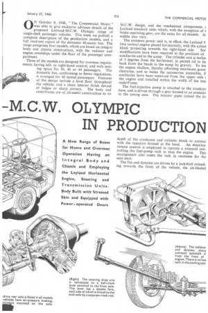
When development has been satisfactorily completed, several pairs of master gears are made for testing each pair of production gears, both before and after hardening. For this, the latest type of Gleason V and H (vertical and horizontal) machine provides a running test of the mating characteristics of the teeth under contact load, either with the normal shaft settings or with the shafts offset vertically and horizontally.
The teeth are painted with a marking compound and run for a few seconds, after which the bearing contact areas can be clearly seen and measured. When gears from the production line are tested, the production wheel is checked with the master pinion and the production pinion with the master wheel.
A bevel pinion is machined in two operations on " paired " machines which are identical, but which have cutters of different diameters for cutting the concave and convex tooth faces. The Gleason machines employed have settings in 12 planes and the necessary
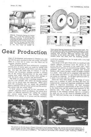
Some typical bearing characteristics of spiral-bevel teeth. The gears should have light-load bearing areas as indicated in inset A, and full-load areas as in inset B. C to E show contact areas resulting from incorrect differences between the spiral curvatures of the pinion and wheel. G and F show bias contacts which may result from the hardening process.
tooth-form modifications can be made with a very high degree of accuracy.
The spirals of the gear-wheel teeth are machined with slightly different curvatures from the spirals of the pinion, and this " mis-match of the cutter radii" again requires great accuracy in manufacturing methods. The machines used are formate roughers and formate finishers with cutters having a series of blades arranged in a circle. One tooth cut is completed with each turn of the cutter and there is a gap between the first and last blades for indexing. In the final operation 0.007 in. is taken from each side of a tooth.
There has been little change in the design of worm gears over a number of years, but there has been one comparatively recent and important modification which relates to improved lubrication. As load increases there is a progressive displacement of the worm parallel to the wheel axis, and the contact load increases on the entering side. This tends to restrict the supply of lubricant to the meshing surfaces and as a corrective the teeth are cut, or the worm is adjusted axially, so that the light-load bearing area is towards the leaving side.
ON October 8, 1948, "The Commercial Motor" was able to give exclusive advance details of the proposed Leyland-M.C.W. Olympic range of single-deck passenger vehicles. This week we publish a complete description of the production models, and a full road-test report of the domestic 40-seater bus. The range comprises four models, which are based on integral body and chassis construction, with the radiator and engine amidships under the floor of the passenger compartment.
Three of the models are designed for overseas requirements, having leftor right-hand control, and with seating space for 36, 40 or 44 passengers. The domestic bus, conforming to home regulations, is arranged for 40 seated passengers. Features of the design include a level floor throughout the vehicle, and a clean interior finish devoid of ledges or sharp corners. The body and underframe are of all-metal construction to an
M.C.W. design, and the mechanical components E. Leyland standard units which, with the exception of t brake operating gear, are the same for all models. A) widths also vary.
The common power unit is, in effect, the Leyland 9. litre vertical engine placed horizontally, with the cylind
block projecting towards the right-hand side. Sot modifications have been required in the positions of auxiliaries and to the sump. The cylinder axis is inclini at 3 degrees from the horizontal, to permit oil to fe( back from the heads to the sump by gravity. To ke( the engine shallow, thereby affording maximum grour clearance, and to make the accessories accessible, tl auxiliaries have been removed from the upper side the engine and installed within the width of the mai underframe.
The fuel-injection pump is attached to the crankca! base, and is driven through a gear housed in an extensio to the timing case. The injector pipes extend the fu