


The New Fiat Omnibus Chassis.
Page 18

Page 19
If you've noticed an error in this article please click here to report it so we can fix it.
The latest addition to the different types of motorbuses in the metropolis is the t907 Fiat chassis. The new pattern departs in many important details from the previous design. The chief points to note are that the engine is placed beneath a bonnet, instead of, as formerly, being beneath the driver's seat. Lubrication of the engine has been altered from a gravity-feed system to a simple and reliable form of pressure feed. The framework throughout is stronger, whilst the springs are now made longer and yet are stiffer than before. The only point of difference in the gear box is the widening of the faces of the wheels, and a general strengthening of the casing and shafts. These chassis are constructed at Turin, in Italy, and the show rooms of the company are at 37, Long Acre, W.C.
The engine, which develops 4oh.p. at 1,200 revolutions per minute, has four cylinders, each of which has a bore of 125mm., whilst the piston stroke is 145mm. The pistons are long, and are each fitted with four cast-iron rings. Solid connecting rods are employed, and the crankshaft, which is fur-MA-Rd with a long central bearing, is 2 inches in diameter : the central bearing is attached to the upper half of the crank chamber, whilst the two end ones are fixed to the lower half of the case, thus allowing the latter portion to be removed without taking down the crankshaft. Mechanically-operated valves are fitted, and these are actuated by two camshafts, driven from the forward end of the crankshaft by fibre gear wheels; these wheels were not previously enclosed, but in the new pattern of chassis they revolve in a dustproof and oil-tight aluminium casing. A large honeycomb radiator is fitted, and the water-circulating pump, which is a centrifugal one, is driven by gear from the forward end of the near-side (exhaust) camshaft. The pump has a long gland, and the front end of the revolving
spindle runs in a bush which is eccentric in its bearing, so that the two gear wheels can be made to intermesh correctly. The usual fan is absent, as it has been found that.
owing to the efficiency of the radiator and pump, one is unnecessary. The carburetter is entirely automatic in its action, and a feature of its design is a tapered needle, which operates within the jet, and works in conjunction with the
' throttle valve; when the latter closes, the needle also falls with it, and, more or less, according to the position of the throttle valve, cuts off the supply of petrol passing through
through a pipe, which passes between the two central cylinders, and is furnished with a long sleeve that surrounds the exhaust pipe. A filter is placed beneath the float cham ber, to keep back any sediment which might pass into the jet. The governor for the engine is carried at the front extremity of the exhaust camshaft, which is hollow, and centains a steel rod ; this rod is capable of being moved longitudinally by the governor, and is connected to the throttle by a light transverse shaft running across the back of the engine, and actuating the throttle valve by suitable steel rods and bell cranks.
As previously mentioned, the lubrication of the engine on the 19°7 model chassis is by a forced-feed system; this is at once simple and accessible. A reservoir, holding about one gallon of oil, is placed in the centre of the dash. Inside the oil-box, and running longitudinally, is a light shaft carrying seven cams, giving a stroke of, approximately, inch.
Beneath the cams are seven pump barrels and plungers, the latter being forced upwards, and in contact with the faces of the cams, by spiral springs. The necessary verticallyreciprocating action of the small plungers is obtained by means of a worm wheel attached to the camshaft, and driven from the engine by a cat-gut belt. Oil leads are taken from the bottom of the pump barrels to various parts of the engine four tubes supply the engine cylinders and enter them at a point just below the lowest piston ring, when at the bottom of the stroke, whilst the other three pipes convey oil to the three crankshaft bearings. Magneto ignition is used, and the magneto is bolted to a bracket near the front of the engine on the right-hand side. The ignition is governed, and, as the speed of the engine increases, so the governor automatically advances the time of sparking. The bus-bar is provided with a shorting switch for emergencies.
The aluminium base chamber is divided into two oil sections by a web, and the engine is bolted to a strong subframe, constructed from channel steel. A steel apron extends from the front of the engine to a point coincident with a vertical line dropped from the transverse gear-changing rod; this prevents oil from dropping on the road. The transmission system is well designed for its work. A
Hele-Shaw multiple-disc clutch, having 32 plates, is placed just behind the fly-wheel; it may appropriately be mentioned here that the fly-wheel has a diameter of 2 feet 3 inches, and is cast with vanes, which draw the air through the radiator :End over the engine The propeller shaft is i inch in diameter ; it has two couplings, and this allows of the central portion of the shaft to be dropped when required. The gear box is a massive aluminium casting, with the differential casing cast integrally with it. The forward end of the box is supported by a cradle extending across the frame, whilst the back end is bolted to one of the straight channel-steel cross members. Four speed ratios are furnished; these are of the sliding type and move longitudinally on the first shaft and are guided by feathers. The different speeds are changed by a lever, working in a gate, and this operates on one of three selector rods. The differential gear has two pinions, and all the shafts in the gear box are provided with ball bearings. The outer ends of the differential shaft, also, have ball bearings, whilst a screwed thrust-cap is placed on each side of the rearward portion of the gear box, to take up any end wear in the differential gear. The small sprockets on the transverse shaft have 17 teeth, whilst the larger ones, upon the back wheels, have 40 teeth. Roller chains are used, having a pitch of 1/ inch.
Ample brake power is provided, and all the parts are well arranged. The foot brake is a duplex one--that is to say, two drums and bands are employed. The first drum is it inches in diameter, and is placed on the forward end of the secondary shaft in the gearbox; the second is placed upon the differential shaft, between the gear box and one of the side members of the frame. These brakes are connected together, and are compensated. Moreover, the drums are water-cooled, and the water is kept under pressure in a cylindrical tank by the exhaust gases. The hand brake is very powerful; it is of the internally-expanding type, and easily adjustable, whilst the drums are entirely enclosed.
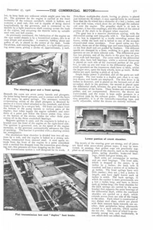
The details of the steering gear are strong, and all joints are fitted with screw-down grease cups; it may be mentioned, in passing, that grease cups are practically supplied on all moving parts of the chassis, such as the steering Joints, spring shackles, brake-rod bearings, clutch and gear levers, etc.
Both axles are rectangular in section, and are steel forgings. The front axle, which is dropped in the centre, is 2i inches by 3 inches ; the back axle is cranked, and has a section of 2i inches by 31 inches. The front springs have very little camber ; they are 3 feet 4 inches in length, and have eight leaves each af inches in width. The back springs, in which the camber is more pronounced, are 4 feet 2 inches long, and have It) leaves each 3i inches long ; the front shackles for the back springs are carried by the same bracket that supports the outer bearings of the differential shaft, whilst the rearward shackles are carried on a shaft, which extends across from one side of the frame to the other. Each wheel is constructed of two dished steel discs, which are placed with their concave faces towards one another, their peripheries being afterwards riveted to a steel sub-rim, which carries the tire rim. This form of wheel is an extremely strong one, and, incidentally, is one which does not collect mud.