


Self-contained Jacks for Heavy Vehicles
Page 54
If you've noticed an error in this article please click here to report it so we can fix it.
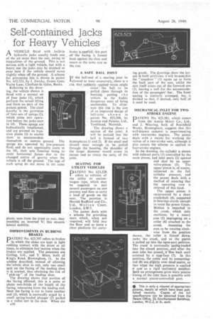
A VEHICLE fitted with built-in hydraulic jacks usually loads one of the set more than the rest, owing to inequalities of the ground. This is not serious. with a light vehicle, but with a heavy one the jacks may be strained or even bent if the vehicle should move, slightly' when off the ground.' A scheme for preventing this is shown in patent No. 623,523, by J. Zwicky, Green Gate, Vache Lane, Chalfont-St.-Giles, Bucks.
Referring to the drawing, the: vehicle shoWn is fitted with a normal set of four jacks (1), which perform the actuallifting and farm no part of the present patent. The chief novelty IS the proVision of four sets of Sphags (2), which come into operation before the jacks start to lift. These sprags,are hydraulically lengthened, and are pivoted on trunnion fates .(3) to enable them ' to accommodate themselveS to uneven ground. The sprags are operated by low-pressure fluid, and do not appreciably assist in the lift, their sole function being to resist' horizontal forces due to the changed centre of gravity when the vehicle is off the ground. The legs of each sprag do not move in the same
IMPROVEMENTS IN RUBBING BRAKES
PATENT No. 623,797 refers to brakes in which the shoes are kept in light rubbing contact with the drum at all times, to eliminate lost'motion when the brakes are applied. The patentees are
,and T. Mace, both of King's Road, Birmingham, 11. In the schErne described, instead of allowing the:whole shoe to rub, only one small spot -on 'the 'facing of the leading shoe is hi contact, thus obviating the risk of "pick-up ". of the leading shoe. The drawing shows that portion of the" facing affected; this is a point at abdiat two-thirds of the length of the facing, Measuring from the leading end. Here the facing is cut to form another end (1),which is outwardly urged by a small spring-loaded plunger" (2) guided in a radialsloi in the shoe. When the s36 A SAFE BALL JOINT
I F the ball-end of a steering joint be allowed to wear excessively, there isarisk that suddenly applied" strain might
cause 'the ball to be pulled clean through its housing, putting t h e vehicle in the highly dangerous state of being unSteerable. To elimi nate this risk is the aim Of an improved design of ' ball-joint shown in
-patent No. 623,506, by
Jermyn and Pointer, Ltd., . Tombland, Norwich.
The drawing shows a section of the joint; it will be noticed that the 'ball is formed of two hemispheres (1 and 2). If the small end should wear enough to be -pulled through the, housing, the shoulder of the larger diameter would arrest its escape and so retain the unity of the joint.
SEATING FOR UTILITY VEHICLES DATENT N. 623,528.
. refers to vehicles of the utility or stationwagon type, which may be required to seat several passengers on one journey and then to carry a load of goods on the next. The patentee is Harold Radford and Co,, Ltd., M el t on Court, London, S.W.7.
The patent deals with a scheme for providing seats which, when not required, will fold into the floor and so leave a clear platform for carry ing goods. The drawings show-the layout in both"positians; it will be seen-that the "trapdoor" (1) opens up to form the hack part of the seat, whilst the seat itself arises out of the forward one (2), leaving a well for the accommodation of the passengers' fee, The front seating is similarly arranged, but( is divided so that, if desired, only half of it need be used.
MECHANICAL INLET FOR TWOSTROKE ENGINE
PATENT No. 623,381, which comes from the Austin Motor Co., Ltd., and J. Weaving, both of Northfield Works, Birmingham, suggests that this well-known concern is experimenting with two-stroke engines. The patent deals with a means for working the valves of a two-stroke unit, although it also covers the scheme as applied to four-stroke engines. ' In the drawing, the cylinder is shown
with exhaust ports (1) controlled by the main piston, and inlet ports (2) opened and shut by an upper valve-piston (3). The upper piston is, of course, subjected to the full cylinder pressure, and the paten/ deals with, a method of ensuring "that the operating cam is relieved of this load..
The upper piston is reciprocated by a short crankshaft (4), supported in bearings sturdy enough to resist the power forces. Motion is imparted to the crank, which only oscillates, by A rotary cam (5) impingeing on a roller (6) attached to the crank. Assuming the cam to be rotating clock
wise from the position shown, the roller is forced dowo,
rocks the, crank, and so the piston
is pulled up into the open-port position.
The crank is torsionally spring-loaded into the closed position,...and after the earn lobe has passed,. it flies back until ..arrested by a stop-face (7). In this position, the crank and its connecting rod (8) are,slightly over dead oentre, so that whets the high pressure is applied it acts as a rigid stationary member. Such an arrangement gives more precise timing of the inlet than is possible with a normal piston-controlled port.
• This is only a resume of.appropriate patents, details of which have been published recently. Copies of the full specifications can be obtained from the Patent Office, 25, Southampton Buildings, London, W.C.2, at 2s. each.