Clutch Specialist
Page 34

If you've noticed an error in this article please click here to report it so we can fix it.
Announces
Centrifugal Model
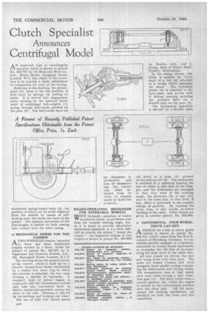
AN improved type of centrifugally operated clutch is shown in patent No. 525,777 by the Borg and Beck Co., Ltd., Brock House, Langham Street, London, WI. The object of the invention is to provide a ready adjustment to compensate for wear of the facings.
Referring to the drawing, the presserplate (4), when in the free position, is held away by springs (3) pulling on studs. It is moved into engagement when running by the outward movement of centrifugal bob-weights (1) acting through bell-cranks pivoted on the. pins (5). The bell-cranks have for
abutments spring-loaded bolts (2), the position of which can be easily adjusted from the outside by means of selflocking nuts; this forms the basis of the patent. The ultimate movement of the bob-weights is limited by their coming into contact with the outer casing.
A MECHANICAL HORSE FOR THE FARMER
ATWO-WHEELED tractor, intended to draw any farm implement usually worked by a horse, forms the subject of patent No. 525,271 by S. Opperman and Ganwick Estates, Ltd., 70a, Basiughall Street, London, E.C.2.
The drawing shows the general layout of the tractor, which is built up on a circular channel-iron frame surrounded by a similar free outer .ring to which the drawbar is attached, the two rings forming a species of turntable. A standard type of petrol engine is employed, and the transmission system may take any convenient form; as shown, chains and sprockets convey the drive to the axle. Steering is effected by declutching and braking one wheel.
The use of only two wheels makes for cheapness in production, and ease of manceuvring; the tractor can, when detached from its work, be wheeled about by hand like a barrow.
BRAKE-OPERATING MECHANISM FOR STEERABLE WHEELS
WITH hydraulic operation of brakes on steered wheels, no problems arise from the variable steering angle, but, as it is usual to provide alternative mechanical operation, it is a little difficult to convey the action "round the corner." An improved scheme in this respect is shown in patent No. 525,853
by Bendix, Ltd., and J. Irving, both of King's Road, Tyseley, • Birmingham.
In the design shown, the brake is applied by r•-zovement of a rod (4) attached to a wedge which separates the shoes. The hydraulic piston (5) is attached to the back-plate, and moves with it during steering, receiving the pressure fluid via a flexible pipe on the port (3)
The mechanical operation is effected by a flexible cable (2) fitted to a yoke (1) pivoted on the pull-up rod (4). The mechanism is enclosed in a spherical housing the axis of which is also that of the kingpin, and the dimensions are arranged so that over most of the working range, the pivot-pin (6) is also very near to the same axis, so that little, if any, effect is noticeable in the angular change of position. By locating the pivet thus, it also avoids excessive bending of the cable. Other details are given in another patent. No. 525,852.
A CONTINENTAL FOUR-WHEELDRIVE LAY-OUT
ADESIGN for a bus or heavy goods vehicle is shown in patent No. 525,711, which comes from the M.A.N. concern of Nurnberg, Germany. It constitutes another example of a tendency, noticeable in several recent disclosures, to re-employ the old idea of incorporating the final drive in the wheel hub.
All four wheels are driven, the rear pair being fitted with twin tyres. The axles are forged I-beams and carry alongside them smaller casings containing the differentials and driving shafts. The transmission runs at high speed, each road wheel having a spur reduction gear (1). The drive comes from a central gearbox (2), whilst the engine is carried in the conventional position over the front axle. All the parts, except the steering mechanism, are identical on both the front and rear assemblies.


