


Giving "Feel" to Servo Brakes
Page 68
If you've noticed an error in this article please click here to report it so we can fix it.
A R6unze of Recently Published Patent Specifications
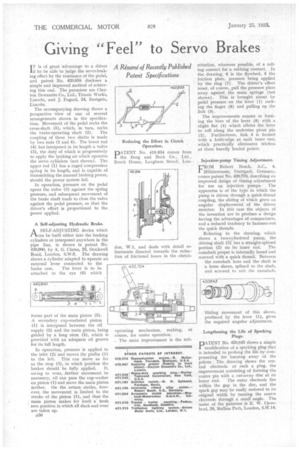
I T is of great advantage to a driver if he be able to judge the servo-braking effect by the resistance of the pedal, and patent No. 420,858 discloses a simple and improved method of achieving this end. The patentees are Clayton Dewandre Co., Ltd., Titanic Works, Lincoln, and J. Fagard, 24, Eastgate, Lincoln.
The accompanying drawing shows a perspective view of one of several arrangements shown in the specification. Movement of the pedal rocks the cross-shaft (5), which, in turn, rocks the brake-operating shaft (2). The coupling of these two shafts is made by two rods (1 and 4). The lower rod (4) has interposed in its length a valve (3), the duty of which is progressively to apply the braking air which operates the servo cylinders (not shown). The upper rod (1) has a caged compression spring in its length, and is capable of transmitting the manual braking power, should the power system fail.
In operation, pressure on the pedal opens the valve (3) against the spring pressure, and subsequent movement of the brake shaft tends to close the valve against the pedal pressure, so that the driver's effort is proportional to the power applied.
A Self-adjusting Hydraulic Brake.
A SELF-ADJUSTING device which
can be built either into the braking cylinders or interposed anywhere in the pipe line, is shown in patent No. 420,900, by A. G. Clama, 28, Stockwell Road, London, S.W.9. The drawing shows a cylinder adapted to operate an external lever connected to the brake cam. The lever is to be attached to the eye (6) which forms part of the main piston (5). A secondary cup-washerecl piston (1) is interposed between the oil supply (2) and the main piston, being guided by a long stem (4), which is provided with an adequate oil groove for its full length.
In operation, pressure is applied to the inlet (2). and moves the pistbn (1) to the left. This can move as far as the stop (3), in which position the
brakes should be fully applied. If, owing to wear, further movement be necessary, oil can pass the cup-washer on piston (1) and move the main piston farther. On the return strcike, however, the movement is limited to the stroke of the piston (1), and thus the main piston makes for itself a fresh zero position in which all slack and wear are taken up.
n50 operating mechanism, making, of course, for easier operation.
, The main improvement is the sub
stitution, wherever possible, of a rolling contact for a rubbing contact. In the drawing. 6 is the flywheel, 5 the friction plate, pressure being applied by the ring (7). The driver's effort must, of course, pull the pressure plate away against the main springs . (not shown). This is brought about by pedal pressure on the lever (1) rocking the finger (8) and pulling on the link (3).
The improvements consist in forming the bore of ,the lever (8) with a slight flat (4) which allows the lever to roll along the undersize pivot pin (2). Furthermore, link 3 is formed with a knife-edge at each inner end, which practically eliminates friction at these heavily loaded points.
Injection-pump Timing Adjustment.
rROM Robert Bosch, A-C., 4,
Militarstrasse, Stuttgart, Germany, comes patent No. 420,704, describing an improved design of timing adjustment for use on injection pumps. The apparatus is of the type in which the pump is driven through a quick-thread coupling, the sliding of which gives an angular displacement of the driven member. In this case the objects of the invention are to produce a design having the advantages of compactness, and a reduced tendency to hammer-out the quick threads.
Referring to the drawing, which shows a two-cylindered pump, the driving shaft (3) has a straight-splined portion (2) on its inner end. The camshaft proper is internally bored and screwed with a quick thread. Between the camshaft bore and the shaft is a loose sleeve, splined to the shaft, and screwed to suit the camshaft.
Sliding movement of this sleeve, produced by the lever (1), gives the required angular adjustment.
Lengthening the Life of Sparking Plugs.
PATENT No. 420,845 shows a simple modification of a sparking plug that is intended to prolong the life by cornpensating for burning away of the points. The drawing shows the central electrode of such a plug, the improvement consisting of forming the centre pin with a cut-away disc at its
lower end. The outer electrode lies within the gap in the disc, and the spark gap may be easily restored to its original width by turning the centre electrode through a small angle. The name of the patentee is E. W. Cleveland, 28, Mullins Path, London, S.W.14.