


Patents Completed.
Page 22
If you've noticed an error in this article please click here to report it so we can fix it.
Albion Chain Flexible Coupling. Challiner Solid Tires. Improved Magneto Construction. Irreversible Steering Gear.
Copies of complete specifications of the patents published on this page can be obtained from the Sales Branch, Patent Office, Holborn, W.C., at the cost of .sixpence for each specification.
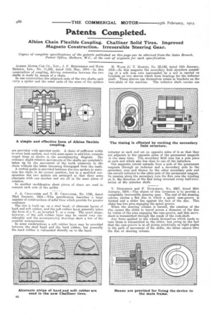
ALBION MOTOR CAR CO., LTD., J. F. HENDERSON and HANS RENOLD, LTD., No. 11,552, dated 11th May, 1914.—In this construction of coupling, driving connection between the two shafts is made by means of a chain.
In one construction the adjacent ends of the two shafts each carry a spider and the outer ends of the arms of the spiders are provided with sprocket teeth. A chain of sufficient width to cover both spiders, and with some spare in addition, extends round them as shown in. the accompanying diagram. The ordinary slight relative movements of the shafts are completely taken up by the movement of the teeth relatively to the chain without the latter becoming disengaged from the teeth. A central guide is provided between the two spiders to maintain the chain in its correct position, but in a modified construction the two spiders are arranged so that their arms alternate with one another and are all in the same plane of rotation.
In another modification short pieces of chain are used to connect each arm of the spider. J. A. CHALLINER and T. H. CHALLINER, No. 1726, dated 22nd January, 1914.—This specification describes a large number of constructions of solid tires which provide for greater resilience.
The tire is built up, on a steel band, of alternate layers of hard and soft rubber, and the soft rubber layer generally takes the form of a V, an inverted V, or a cross. The exact shape, however, a the soft rubber layer may be varied very considerably and the accompanying drawings show a few of the possible arrangements.
In some constructions a soft rubber layer may be provided between the steel band and the hard rubber, but generally the hard rubber is vulcanized directly on to the band.
H. WADE (C. T. MASON), No. 23,142, dated 13th January, 1914.—In this magneto the secondary field structure consisting of a soft iron core surrounded by a coil is carried on brackets on two sleeves which form bearings for the inductor shaft. These sleeves can themselves rotate in brackets on the base-plate of the machine. The inductor shaft carries one
inductor at each end set on opposite sides of it so that they are adjacent to the opposite poles of the permanent magnets at the same time. The secondary field core has a pole piece at each end which also lies close to one of the inductors.
The magnetic circuit extends from a pole of the permanent magnets through an inductor and a secondary pole to the secondary core and thence by the other secondary pole and the second inductor to the other pole of the permanent magnet. In passing along the secondary core the flux cuts the winding on it, the direction of the flux being reversed every half-revolution of the inductor shaft.
T. DIcitricsoN and F. DICKINSON, No. 2067, dated 26th January, 1914.—The object of this invention is to provide a completely irreversible steering gear. The end of the steering column carries a flat disc in which a spiral cam-groove is formed and a, slider lies against the face of the disc. This slider has two pins engaging the spiral groove. When the steering column is turned, the rotation of the disc causes the slider to travel across a diameter of the disc by virtue of the pins engaging the cam-groove, and this movement is transmitted through the crank of the rock-shaft. Any force applied to the wheels themselves which tends to turn them is transmitted to the slider, but owing to the fact that the cam-groove is at all points practically at right angles to the path of movement of the slider, the latter cannot turn the disc or steering column.