


• I55.—Removing Rear Wheel Driving Flange on 30 cwt. Albion.
Page 28
Page 29
If you've noticed an error in this article please click here to report it so we can fix it.
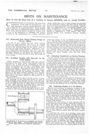
On the 30 cwt. Albion the rear wheel driving flanges are each provided with two e'sin. tapped holes, into which setscrews can be inserted in order to force the driving flange off the wheel, after removing' the nuts from the bolts. Sometimes, how'ever, theseholes become filled with dirt, and may not be noticed by the repairer, who may cause considerable' damage to the flange by hammering at the bolts, or by endeavouring to force the flange off with a chisel.
156.—Avoiding Trouble with Big-ends on the Tylor Engine.
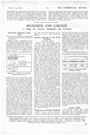
Where trouble is 'experienced with the big-end , bearings of the Tylor engine, this usually occurs to big-end. No. 4, and can be attributed to the oil groove in the rear main bearing or crankshaft being either too shallow, or, in some cases, being altogether overlooked. This happens more often on reconstructed vehicles which have had their crankshrifts reground and the bearings remetalled. The groove in the shaft actually becomes more shallow each time the shaft is reground, and it should be deepened to the same amount as the groove in a new crankshaft.
There, is no need to deal with the centre or front main bearings, as the hole and groove in each of these bearings comes directly in line with the hole in the crankshaft, and if the grooves in this bearing are in. wide and 3-32 in. deep, there is not much to fear. The diagrams may help those who have experienced trouble with the No. 4 big-end. The oil enters the bearing through the in. hole marked A, and travels in the direction of the arrow, whilst the groove in the -crankshaft travels from B to C. The oil then continues along.grooVe I) to the big-end beaking, and care should be taken to see that the groove in the crankshaft meets that in the bearing. Should the big-end run, do not be satisfied by merely, having a new one fitted ; have the rear main bearing removed, and make certain that the grooves are actually there, and that there' are no fancy grooves such as those shown on the dotted lines, which only cause leakage from the , rear main bearing.
157.—Adjusting Crankshaft on Clayton Steamer.
On the Clayton steam wagon engine, owing to wear on •the brasses, it sometimes' beComes necessary to raise the crankshaft in order to lift. the drivitg gears a little farther out of the foots of the' gears on the second motion shaft. The best method of doing this is compIetely to remove the crankshaft. aid, brasses. The latter are'circular shaped and I fit into similarly shaped brackets and are provided with ring oilers. Now obtain some copper 'strips of the required length and thickness and solder.these at each side of the gap alloWed for the oil eireidating ring. The brasses can then be bedded into the brackets, the surplus metal at the extremes filed down and the whole made a. very firm job. On no account must one side only be packed up, as, if so, the crankshaft will be thrown out of line and the gears will not mesh properly. The copper strips also should be firmly secured, otherwise they tend to work out and prevent the oil ring from rotating.
158.—Adjusting Engine of 4 ton. Bristol. Should it be necessary to examine a piston of the engine of _the 4 ton Bristol chassis, all that is required is to disconnect the big-end, when the piston and connecting rod may be drawn down and out without disturbing the crankshaft or any other part. The replacement of the engine is greatly facilitated by the wide bell mouth turned in the base of each cylinder, which gradually forces the rings down into their grooves and does away with the need for special ring clamps. . . Between the two halves of each big-end will be found laminated brass shims, 'composed of sheets of brass foil about .003 in. thick. If the bearing is at all slack, remove one of these brass sheets with a sharp knife, and replace the bearing. If the slackness is still a,pparent, remove a further sheet. The use of these shims ensures that the faces remain parallel. In replacing the parts of a bearing, greatcare should be exercised to see that the numbers stamped on the brass cap correspond and come into line with the same number on the opposite half of the bearing. Care should be 'taken with regard to the dipper found on each connecting rod cap. These are tended to pick up oil from the troughs immediately below each connecting rod. When the bearings on the latter have been taken up several times, it will be
found that the dipper does not reach as far down as previously, owing to the number of shim strips which have been taken off. It is advisable, therefore, occasionally to make a test by inserting a block of stiff grease in each trough, and arrange with someone to turn the engine whilst the lower half of the crankcase is held up in position. In this way a mark will be made in the grease showing the path of the dipper and itsheight above the trough. It should be arranged that the -extreme point of the dipper stands .5 ram. above the machined edges of the trough. This distance can be adjusted by a paper packing between the trough casting and the bottom of the crank chamber, to which it is bolted.