SPRAGS AND SPR, HOW AND WHY.
Page 12

Page 13

Page 14

If you've noticed an error in this article please click here to report it so we can fix it.
Why the Old Type of Sprag isUnre A Suggested New Forn ly Exchanges One Risk for Another. th. Interesting Features..
THAT NO vehicle should be so constructed where there is a possibility of its getting out of hand and running backwards when changing gears on a steep hill no one will gainsay. With cemmercial vehicles carrying big loads, and even with heavy pleasure cars, there is always a danger of the driver finding himself in a tight corner while climbing steep hills. In the ease of commercial vehicles, these troubles are not always reported to the owner, and, as the owners of such vehicles seldom, or never, drive them, and in many cases never even ride on them, they. are usually unaware of the near shaves which some of their drivers have in hilly country.
It may be said that if brakes are good enough to slop a vehicle when going forward down hill, they should be good enough when running backwards. This, however, is not always the case. It is perhaps not easy to account for this, but in many constructions, when the vehicle is running backwards, there is a tendency for the brakes acting on the wheels to release their hold owing to the ' movement of the back axle due to torque. This movement is only slight, but it is sufficient to render the wheel brakes less efficient than they are supposed to be, and, although the transmission. brake, if it exists, remains unaffected, it is not always sufficient in itself to hold a vehicle where the conditions are exceptional. There is another difficulty in changing gear on hills, and that is, should trouble occur owing to missing the change and the vehicle be brought to a standstill, there is the difficulty, in getting restarted, of coaxing the brakes off and the clutch in at the same time, where no sprag is used. For some reason sprags have been declining in favour for a long time. This is probably due to the fact that no thoroughly reliable form of sprag ha a yet been designed. It is with -this knowledge in mind that we have called attention to the matter of sprags and other devices for accomplishing the same desired object ; namely, the arresting of the backward running without interfering with the forward progress of the vehicle.
Scarcely a month passes but one or more accidents are reported where in each case a vehicle has got out of hand on a gradient and has run backwards, involving loss, damage, and risk. The possibility of such a mischance was well known in the early days, sprags then being commonly fitted to almost all types of motor vehicles. Brakes have been consistently improved, but no effort baa been made to develop that other equally vital safeguard.
Sprags have taken three forms—what we may describe as the "ordinary " sprag, the ratchet sprag, and the roller. A development of the lastnamed 'placed on the market is the Willskotch, . a triangular chock operating in pairs and hinged to the rear axle.
Common Forms of Sprag with Bad Features.
By the term "ordinary sprag " is meant a stiff bar hinged at its front end to the frame and free at its rear end to dig into the ground, and so to stop the backward movement of the vehicle. This device has been found to be so unreliable that one seldom sees it fitted as a standard. Its objections are as follow :—It is necessary that it should have a fairly steep angle, otherwise it will not dig into the ground with certainty. If the angle is too steep the vehicle has a way of "jumping the sprag," which means that the sprag will bury itself to some extent in the ground, especially if the ground be soft, which reduces the angle and brings the sprag near to the perpendicular, and when in this position it is not uncommon for the .vehicle to 'rise enough for the sprag to turn over so that it is inoperative. Should this occur when the driver is relying upon the sprag, he is in a worse position than he would be if it did not exist at all, as then he 'would be more on his guard.
B16
The ratchet type is usually made in the form of an internal set of ratchet teeth formed inside the brake druni in the transmission brake. A pawl is arranged so that it can be lowered to engage these teeth -by gravity, and so stop backward movement. This form cannot be applied if is heavy vehicle has once got away backwards, as its action is not by friction, like that of a brake, but is sudden and positive, and, if applied when the vehicle is in motion backwards, will only result in breaking some part rather than in stopping or even checking movement. Both the common and the ratchet sprags, if used, should be released ready to take up before any trouble occurs; that is to say, at every change of gear made on steep hills. Now, one does no.t anticipate trouble every time such a change is made, and so no one will take the precaution to release the sprag for what seems only a vague chance of it being required. The ordinary man, .therefore, relies upon his brakes to stop him should he muddle a change. Once having got into trouble, he is not able to use his sprag, so, if it be one of the two types mentioned, it is of little use having it fitted.
Roller to Prevent Running Backwards.
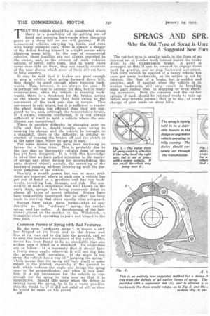
Fig. 1 shows a device which has been used for time on country wagons, and has proved itself to be one of the most effective devices when fitted to heavy motor vehicles. It does not look in keeping
with a modern scientific design, and perhaps on that account is rarely seen applied to motors. It has ancther disadvantage—that it is-not easily operated from the driver's seat. Like other forms,it is very good so long as it is in position before any trouble occurs; but, should the vehicle be actually moving backwards and the roller then brought into position, it will jump the roller. It might be asked: Why not make the roller larger, then it will not be so easily jumped? The answer to this is that, if the roller is large enough for the vehicle not to jump it, it will not act as a: check, but will be forced out of contact with the wheel or the ground, and so will fail to act.
In the design of commercial motor vehicles intended to be offered for sale in all parts of the world, the question of fitting a sprag or some equivalent device is continually cropping up. It must be borne in mind, when considering such questiona, that England is a country with comparatively few really steep hills, and that skilled drivers are plentiful here. In many other eountries, however, these conditions do not prevail, and even in vehicles for home use more attention should be given to seme means of preventing running backwards other than the ordinary brakes. The essential points required-in such a device seem to be to be as follow:—
(1) Extra retarding power, other than, ordinary brakes, to act in a backward direction only.
(2) This power should be of such a nature that it can be applied gradually when backward motion has already begun.
(3) Such device should admit forward motion to be resumed without any act on the part of the driver to release it.
As it is not much good pointing out a disease without suggesting •a remedy, we have obtained the opinion of an engineer who has given the matter his particular attention, and the following are his suggestions and remarks:—
My experience of sprags, or equivalent devices, especially for use in country such as is found in the Colonies, is (says our correspondent) that anything acting upon the road itself, such as an ordinary sprag, is practically useless, as, when on soft, sandy ground, it will bury itself rather than stop the vehicle, and when on stone setts or hard roads such as are found in cities, it will not grip. The roller is more useful, but it has its limits. Both these devices require to be brought into action before the actual backward movement occurs, and, -therefore, they will not prevent unexpected trouble. It is true the very little attention has been given ti either of these d-eviees, and it is• possible that both of them might be improved, but they are not in keeping with the order of present-day thought, so engineers seem to have disregarded them:
• The ratchet sprag_, although more mechanical looking, is perhaps the worst form. of all for commercial vehicles, as there is always the possibility of an inexperienced driver applying it when his vehicle has got out of hand, with disastrous results.
The Least Dangerous Form of Ratchet Sprag.
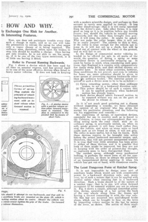
• It is not impossible to design some sort of auxiliary brake which would act ivith considerable power in a backward direction only, and, moreover, be of such a nature that it can be applied with perfect safety when running fast in a backward direction. Such a brake should be of the nature of a ratchet type; that ia to say, will allow forward movement to be resumed without any act to release it. Fig. 2 shows a simple, although somewhat primitive, device, consisting of a bar across the back of the rear wheels slung from the frame, aaul having a tie-rod connecting it with the rear axle. On this bar are mounted two snail-shaped brake shoes, which can be brought to bear on the tyres by imparting rotary motion to the barby means of the lever, as shown. The action of these shall
shaped shoes is such that they will have a very great gripping action in one direction,and will release to some extent when forward motion is resumed.
Fig. 2 shows a better scheme, consisting of a similar bar across the rear, but slung from pivoted links from the frame and pulled forward by means of the bars shown. It will be noticed that the shoe is of special construction, being connected to the link by means of short links, one of which is provided with a quadrant to limit its motion in one direction. This brake can be applied when running in a backward direction, and Fig. 6. The employment of V-shaped brake surfaces for an auxiliary brake to be applied only in em erg encies, would be quite satisfactory,
way ; but, should forward shoe can follow the wheel NO, cause the short links to raatically to release it.
it will stop the ve
hicle in the ordinary motion be resumed, the and rise, and, in doing come into play and huto
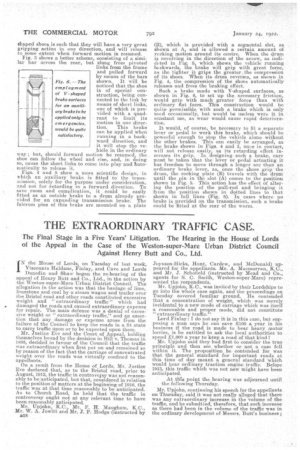
Figs. 4 and 5 show a more scientific design, in which an auxiliary brake is fitted to the transmission, solely for the purpose under consideration, and not for retarding in a forward direction. To save room and complication, it could be easily fitted as an outside brake to a drum already provided for an expanding transmission brake. The fulcrum pins of this brake are mounted on a plate (B), which is provided with a segmental. slot, as shown at A, and is allowed a certain amount of reeking motion around its centre. When the drum is revolving in the direction of the arrow, as indicated in Fig. 5, which shows the vehicle running backwards, the brake will grip with great force, as the tighter it grips the greater, the compression of its shoes. When its drum reverses, as shown in Fig. 4, the compression of the shoes automatically releases and frees the braking effect.
Such a brake made with V-shaped surfaces, as shown in Fig. 6, to set up the necessary friction, would grip with much greater force than with ordinary flat faces. This construction would be quite • permissible with such a brake which is only used occasionally, but would be useless were it in constant use, as wear would. cause rapid deterioration.
It would, of course, be necessary to fit a separate lever or pedal to work this brake, which should be powerful enough to stop the vehicle alone without the other brakes. This can easily be arranged, as the brake shown in Figs. 4 and 5, once in contact, will not release easily, as its retarding effect increases its grip. In designing such a brake, care must he taken that the lever or pedal actuating it has freedom to move through a longer arc than an ordinary brake lever, as, once the shoes grip ' the drum, the rocking plate (B) travels with the drum until the in in the slot (A) comes to the position shown in I4ig. 3. This action has the effect of altering the position of the pull-rod and bringing it from the position shown in dotted lines to that shown in full lines (Fig. 5). In cases where no brake is provided on the transmission, such a brake could be fitted at the rear of the worm.


