


French Chassis has Cab Under Frame
Page 68
If you've noticed an error in this article please click here to report it so we can fix it.
ANOVEL design for a. lorry comes . in patent No. 631,764, from R. Ruelle, 5, rue Manin, Paris,which shows a chassis having a flat top free from obstructions in all directions. The atm of the design is to enable beams, girders and the like to be transported without th risk of their bending under
their own weight
The drawing shows the main features in the design, in which engine, transmission, and driver's cab are all located below; floor level: The controls present a problem, but the patentee suggests ihat. cables sliding inside tubes would be the answer. Such a vehicle would be easy to load, as access is good from front, rear and sides.
AN ENGINE WITH ROTARY CYLINDER HEAD
AN engine in which the cylinder-head rotates and functions as a valve is shown. in patent No. 632,573 by F. Caudniont Asnieres,. France. The' scheme is said to be equally suited to sparkor compression-ignition engines, working • on either the four-stroke or two-stroke principle.
Referring to the drawing, the cylinder contains a piston-like head (1) which is revolved in a nitrided liner by gearing from a vertical shaft (2). As it revolves, slots inits side uncover port s leading to an exhaust belt -(3) -and an inlet port mot shown).
Ai the upward thrust is considerable, sturdy ball-thrust-races (4) are provided, and relief is given by 'the use of a stiff helical spring inside the thrust races. 'flits spring allows the head to rise approximately 3 mm. under full pressure.
Air.cooling is provided, spaces 5 being traversed by a draught produced by turbine blading on the rotary member. Provision is made for adjusting the position of the head so that the compression can be varied to suit a particular fuel being used.
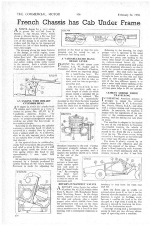
A VARIABLE-RATIO HANDBRAKE LEVER DATENT No. 631,649 comes from
Fodens, Ltd., W. Foden and E. Twemlow, all of Sandbach, Cheshire, and shows an improved design for a hand-brake lever. The aim is to provide a decreasing ratio, high at first to take up slack, and low later to provide a powerful The mechanism is very simple; the lever pulls on a short length of chain (I) which passes round a sprocket (2) on its way to the rodwork. The
sproe k e t is eccentrically mounted so that when the lever is pulled from the position shown, the sprocket hauls the chain fast in relation to lever movement, and a rapid movement is,
therefore imparted to the rod. Further movement gradually reduces the effective diameter of the sprocket, until it reaches the position shown at 4, which is the end of the working range.
The design incorporates a lever-operated ratchet quadrant and pawl to lock the hand brake "on." By arranging the lever horizontally the driver is able to obtain the maximum pull. , ROTARY-CUM-POPPET VALVES
.A ROTARY valve forms the subject CI Of patent No. 632,128, which comes from A. Boorer, 120, Broadwater Street West, Worthing, Sussex. In the design shown, separate rotary valves are used for inlet and exhaust, plus a master poppet valve which shields them from the combustion and acts as the main sealing member. This means that the rotary members can be a free fit in their housing, with a consequent reduction in wear. Referring to the drawing, the single poppet valve is operated in the usual manner, and controls a chamber (1) having twc ports, one leading to the rotary inlet barrel (2) and the other to an exhaust-control barrel (3). The exhaust valve is cross-ported and works in both directions alternately,so that it has to be rotated at one-quarter crankshaft speed. The inlet _valve ,has only one port (4) and the mixture is supplied through its bore, so that this one must rotate at half crankshaft-speed. The aim of the two different speeds is to give a more rapid initial opening of the inlet so that the kinetic energy of the arriving gases helps to fill the cylinder.
CEMENT MIXING WHILE TRAVELLING INTERESTING American practice is 1 divulged in patent No. 631,643, which comes from R. G. LeTourneau Inc., Peoria, Illinois, U.S.A., and deals with a cement mixing and transporting vehicle. In operation, the machine is loaded with the ingredients of the concrete at the commencement of the journey, and the mixing can take place en route.
The machine is adapted to be hauled by one of the well-known LeTourneau two-wheeled tractors, the wheels of which are seen at I. The ingredients are placed in the drum (2) via a manhole (3) at the top. The drum rotates, being carried in a bearing (4) at the front and in a roller-race (5) about midway.
The drum is slowly rotated by an electric motor and reduction gear (6) under the control of the driver. The drum is fitted internally with Archimedian vanes which continually shift the mixture forward, so that it has. little
tendencyto leak from the open rear
end (1). ,
Both • the drum and its cradle are pivoted about point 8,so that it can be elevated after the manner of a gun. This function is useful on buildg work, because it enables the load to be discharged at a high level if need be. The charge is ejected by reversing the direc tion of, the Archirriedian screw. . Thorough rnixing.and a considerable saving in time are two obvious-advantages of operating such a machine.